Mass Air Flow Sensor Wiring Diagram
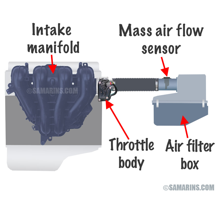
Take a look at the applies to. The maf or mass air flow sensor is a main input to the ecm or engine computer form air intake temperature and flow.

Mass air sensor diagram hooking up a chip.

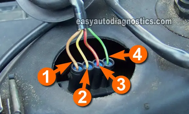
Mass air flow sensor wiring diagram. Luxury mass air flow sensor wiring diagram through the thousands of photos on the net regarding mass air flow sensor wiring diagram picks the very best choices with ideal resolution simply for you and this images is usually considered one of images choices in this ideal pictures gallery with regards to luxury mass air flow sensor wiring diagram. Good and faulty maf. The most common way to test the 5 wire vw mass air flow maf sensor is just to unplug it with the engine running.
Learn how this device is connected to the ecm and vehicle electronics in general. Is the wiring the same as the 2006 mustang. 2007 mustang gt same question as before.
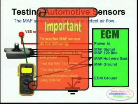
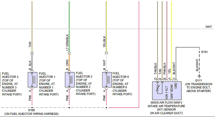
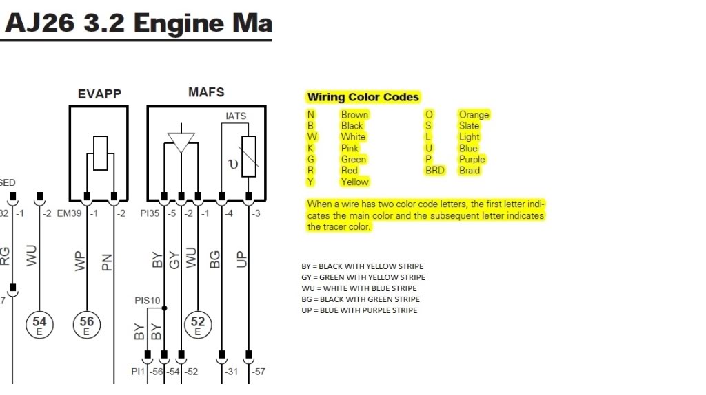
The mass air flow sensors converts the amount of air drawn into the engine into a voltage signal. The following schematic shows a typical circuit diagram of the mass air flow maf sensor system. How to clean a mass airflow sensor in.
How mass air flow sensors work. If the maf is bad either because its not producing a signal or producing an erratic one the cars idle will return to normal and the car will seem to run fine. The primary components of the maf sensor are thermistor a platinum hot wire and an electronic control circuit.
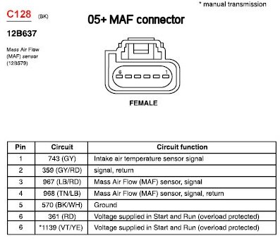
Below is a curve of the mass air flow of a 19l tdi industrial engine afd. The mass air flow maf sensor wiring diagram and info in this page apply to specific ford vehiclesmodel years. Pierburg maf bosch maf converting mgstroke to kghour.
Maf sensor wiring diagram note. Box on the right column to check for specific application info. Step by step guide on how an automotive mass air flow sensor maf works.
The wire colors and the connections mentioned to the ecu are from a 66kw alh engine. The instructions are to find two wires when measured together return 10 read more. Mass air flow sensor page content.
How to test and replace intake air temperature sensor p0110. How to test a mass air flow maf sensor without a wiring diagram ratchets and wrenches. What about mustang gt 1989 mass sensor or density sensor and i need a vacuum diagram layout and a electronic diagram harness layout because i am change this engine 50and 5 speed transin a 1966 m.
Step 1 the mass air flow sensor is designed to monitor the volume of air passing into the engine at any giving time.
 Maf Sensor Wiring Diagrams Youtube
 I Need The Wiring Diagram For The Mass Air Flow Sensor To A 2006

 Part 1 Testing The Vw Passat 98 99 Mass Air Flow Maf Sensor

 Maf Mass Air Flow Sensor Freeautomechanic


 Gm Maf Sensor Wiring Diagram Wire Center Inside Mass Air Flow
 2013 Nissan Frontier Wiring Diagram Further Mass Air Flow Sensor
 How Mass Air Flow Sensors Work Explained In Under 5 Minutes


 Wiring Diagram For Mass Air Flow Sensor Great Installation Of

 Mass Air Flow Sensor Wiring Diagram Allove Me
 Toyota Maf Sensor Voltage Youtube
 Code P0101 Mass Air Flow Sensor Circuit Range Performance

0 Response to "Mass Air Flow Sensor Wiring Diagram"
Post a Comment