Cummins Low Flow Cooling System Diagram
The low flow system has about a 20 degree drop. If i remember correctly the iv are the ones with the low flow cooling system.
0420 E111 Emergency Diesel Generators Chapter 06 Engine
Lower 55 and upper 56 bypass chambers and lower 57 and upper 58 cooling chambers.
Cummins low flow cooling system diagram. Edited by ben in the basin 6292013 2331. The larger drop occurs because the low flow radiator is divided into multiple section sections with the use of baffles in the top and bottom tanks. With the cummins system lower air temperatures from the engine aftercooler also means lower water temperatures to the after cooler hence the requirement for low flow cooling lfc radiators.
They were available into the late 90s and maybe still are. Cools back down after idling. These engines take a special radiator and different sealing rings in the water manifold.
Exhaust system flow diagram. The dual valve thermostat 50 comprises a housing 51 which defines essentially four chambers. Dept 56 display photos.
Personally i love the looks of a bc4 especially a 444. Im not up on the bc 1 but i believe the tiing was different and there was different oil filter setups on each of them. Cummins system diagrams m 11.
The lower the air inlet temperature the higher the air density hence a more dense charge and improved engine efficiency. Cummins reman pushed a big cam 440plus that was basically a latest tech bc3 without the step timing and low flow cooling of a bc4 444. High flow cooling systems typically have about a 7 degree f.
The big cam 3 has the low flow cooling system with the 15 radiator hoses and dual thermostats. The old full flow ones have hoses that are 2 or larger. The flow of coolant through the dual valve thermostat 50 is indicated by the arrows shown.
The 440plus were cummins beige and had a bc3 style aftercooler. Cooling system flow diagram. We had an 89 volvo with a low flow system.
Has new radiator in it runs a little over 200 degrees in a couple of miles. Low flows were relatively late in the big cam production run. Trucking jobs in 30 seconds.
I have a 350 cummins low flow that gets hot under a load. Air intake system flow diagram. Lubricating oil system flow diagram.
The low flow ones have coolant lines to the radiator no bigger than an inch and a quarter or so diameter. Cummins ntc 400 blue smoke. Temperature drop from inlet to outlet.
The big cam 2 has the high flow with the 25 hoses and single thermostat. This engine is a little before my time but i believe if you keep these in checkit should cool ok. Low flow cooling system and apparatus.
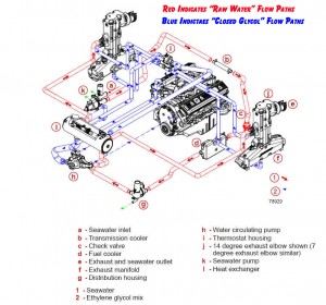 Mercruiser Closed Cooling System Flow Diagram Perfprotech Com
 Cummins Low Flow Cooling Diagram Wiring Diagram Schematics

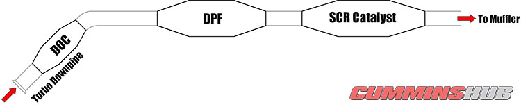
Cummins Tier 4 Technology Overview
Cooling System Flush Turbo Diesel Register
Body Builder Instructions
Application Installation Guide Engine Room Ventilation

 Common Causes Of Engine Overheating And How To Fix Them


How Does A Radiator Overflow Tank Work Quora
 Charge Air Cooling


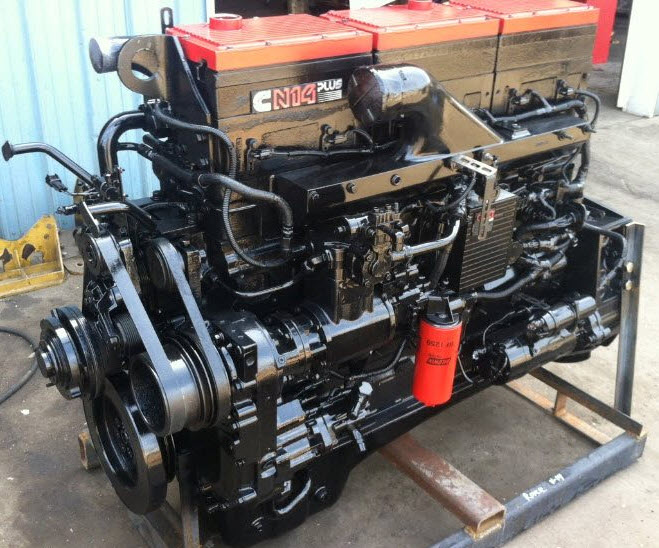 Cummins N14 Specs History And Problems Capital Reman Exchange
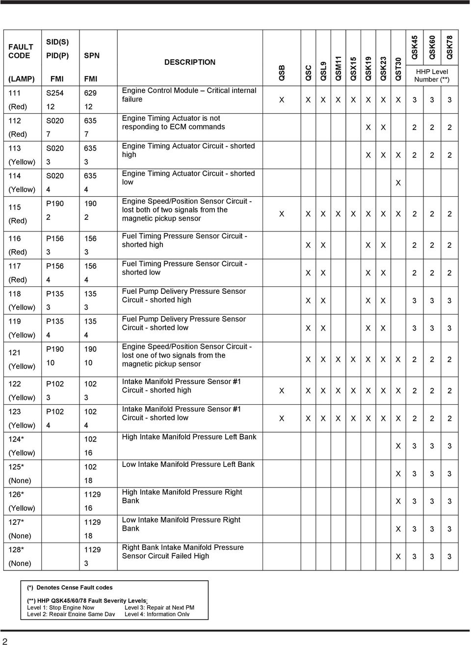
Diagnostic Fault Codes For Cummins Engines Pdf
 Cummins Engine Cooling System Diagram Electrical Schematic Wiring
Low Flow Cooling Radiators Service Procedure
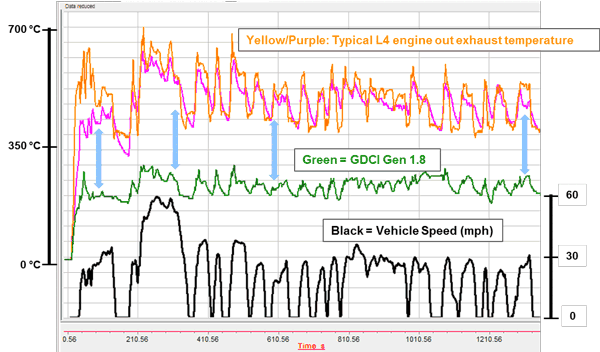 News Conference Report Us Doe 2017 Annual Merit Review
 Ect Sensor Wiring Diagram Youtube
0 Response to "Cummins Low Flow Cooling System Diagram"
Post a Comment