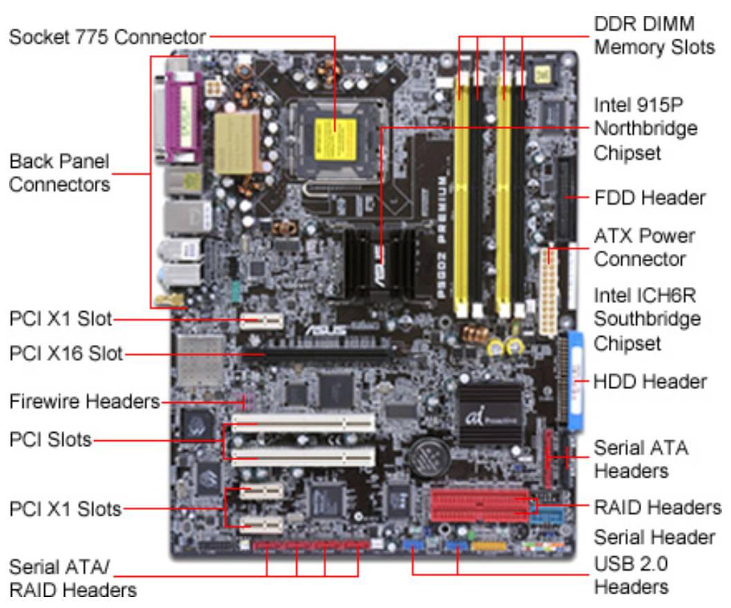
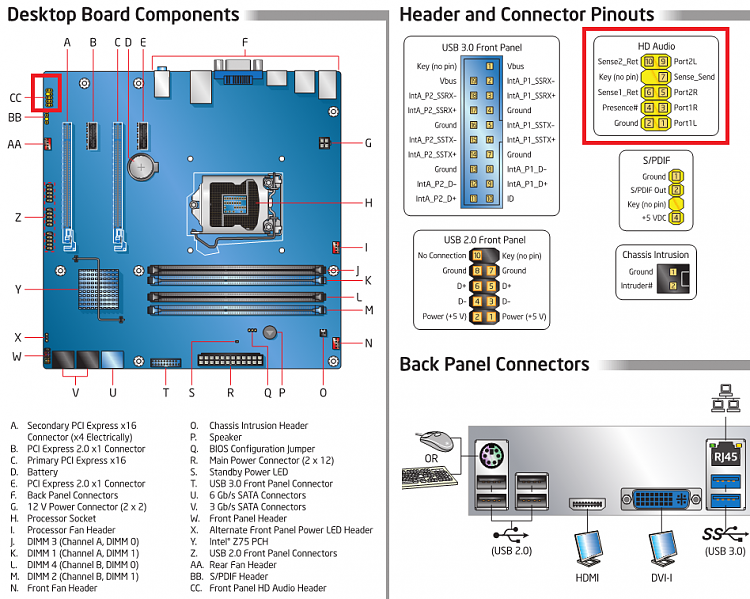
Motherboard Front Panel Connection Diagram
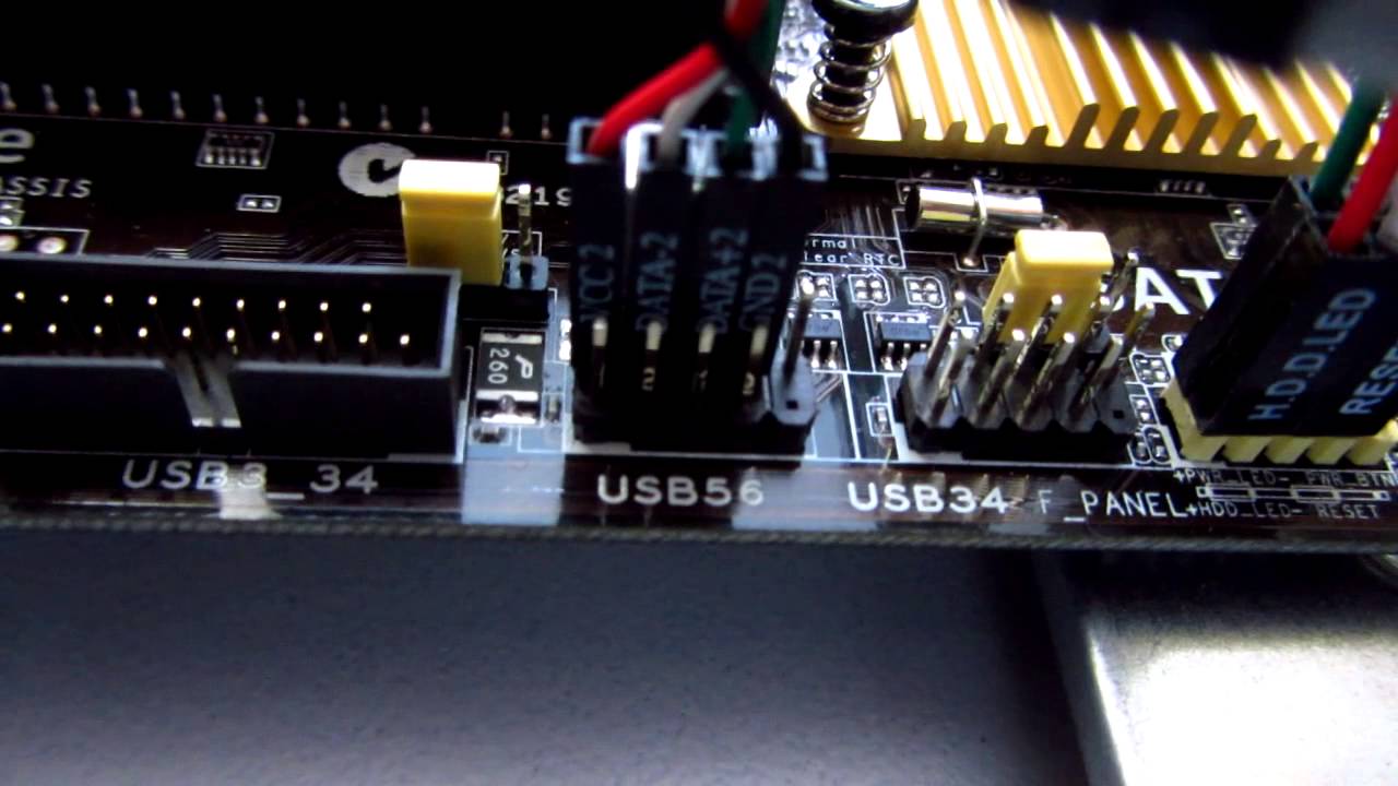
And each header allows for 2 usb connections ie. The pins for usb1 and usb2 are in seperate rows.
 Motherboard Connection Diagram 11 13 Stromoeko De
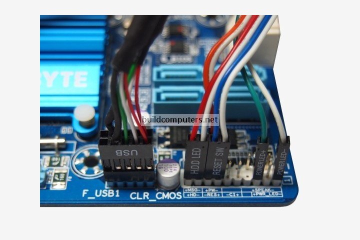
See how to connect front panel connectors to the motherboard.
Motherboard front panel connection diagram. How to connect front panel usb headphone microphone firewire connectors onto motherboard. I have a lenovo thinkcentre m91p q67 is6xm motherboard for a new build. August 2018 page 2 michaelhannanco vga wire color diagram and colors electrical wiring code of to cable engine tools vga wire color.
Fouquin 2016 12 05. The q connector is bundled with selected models. Remove icloud lock in 2 minutes without simwifiapple iddnspassword success jan 2019 duration.
Goodman motherboard wiring color code wiring diagram database atx diagram wiring diagram database usb cable color code goodman motherboard wiring color code. Use this header if your chassis provides only a 3 pin connector to the front power leds. Does anybody have a wiring diagram for this.
I looked on the lenovo website and have not been able to find the pinout layout for power power led etc. Unlock apple recommended for you. Need front panel pinout.
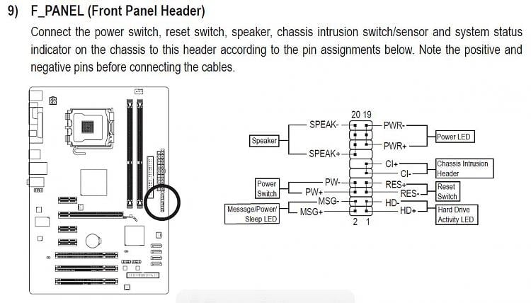
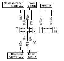
But there are 13 pins in the fpanel area of my board. This includes connecting the power switch reset switch hard drive led light power led light and an internal speaker. Thanks for the diagram though.
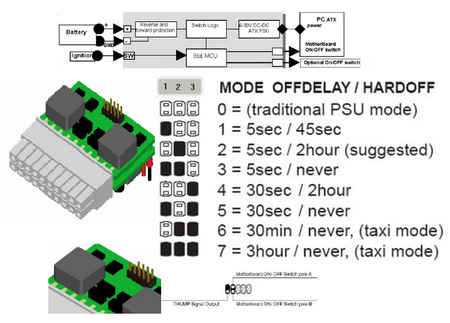
Intel desktop boards also include an alternate front panel powersleep led header. Xps 8900 fpanel wiring diagram trying to install in a new case and need the f panel wiring diagram to connect the power reset and hdd light switches to the pin connectors on the motherboard. Simply plug the.
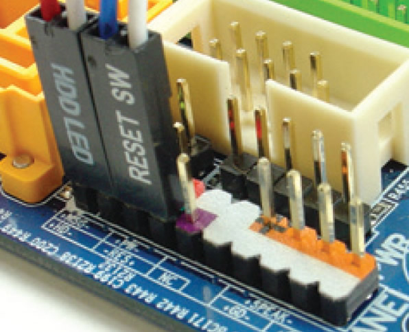
The q connector directly indicates which pin corresponds to which device and which polarity wire needs to be connected to it. Can someone help me find the front panel connector diagram for a hp pro 3500 motherboard brian99 jul 22 2017 346 pm im putting my hp pro 3500 in a different case. Motherboard front panel wiring color.
Simply slot it over the motherboards front panel connector. On most motherboards the usb headerpin out consists of 9 pins arranged in 2 rows.

 Computer Wiring How To Connect Your Computer Wires
 How To Install A Motherboard Installing The Front Panel Wires Of 8
 Gigabyte Motherboard Installation Guidebook


 Usb Front Panel Wiring Diagram Wiring Diagram


 G5 Front Panel Wiring Diagram Wiring Diagram
Front Panel Connector Aray Power Switch Hhd Power Led Reset Switch
Front Panel To Motherboard Connection Windows 7 Help Forums

 Usb Front Panel Wiring Diagram Wiring Diagram
 Configure Front Panel In Zebronics Motherboard Windows 7 Help Forums
Full Atx In An Hp Z400 Workstation Case With Psu And Cpu Cooler


0 Response to "Motherboard Front Panel Connection Diagram"
Post a Comment