System Sensor Duct Detector Wiring Diagram
Wiring for 4 wire duct smoke detector and accessories important notes on 21 sensor to power capability. Variety of duct smoke detector wiring diagram.

Read the system sensor guide for proper use of smoke detectors in duct appli cations a05 1004 which provides detailed information on detector spacing placement zoning wiring and special applications.
System sensor duct detector wiring diagram. R emove the screen by gently grasping on each side and pull. Wiring diagram shown is for dh100acdclp 4 wire duct smoke detector system equipped without a control panel. If the detector is shipped loose for field installation refer to the.
It shows the components of the circuit as streamlined shapes as well as the power as well as signal links between the gadgets. Testing detector alarm cleaning procedures board replacement. 21 sensor to power capability is not available for all innovairflex models.
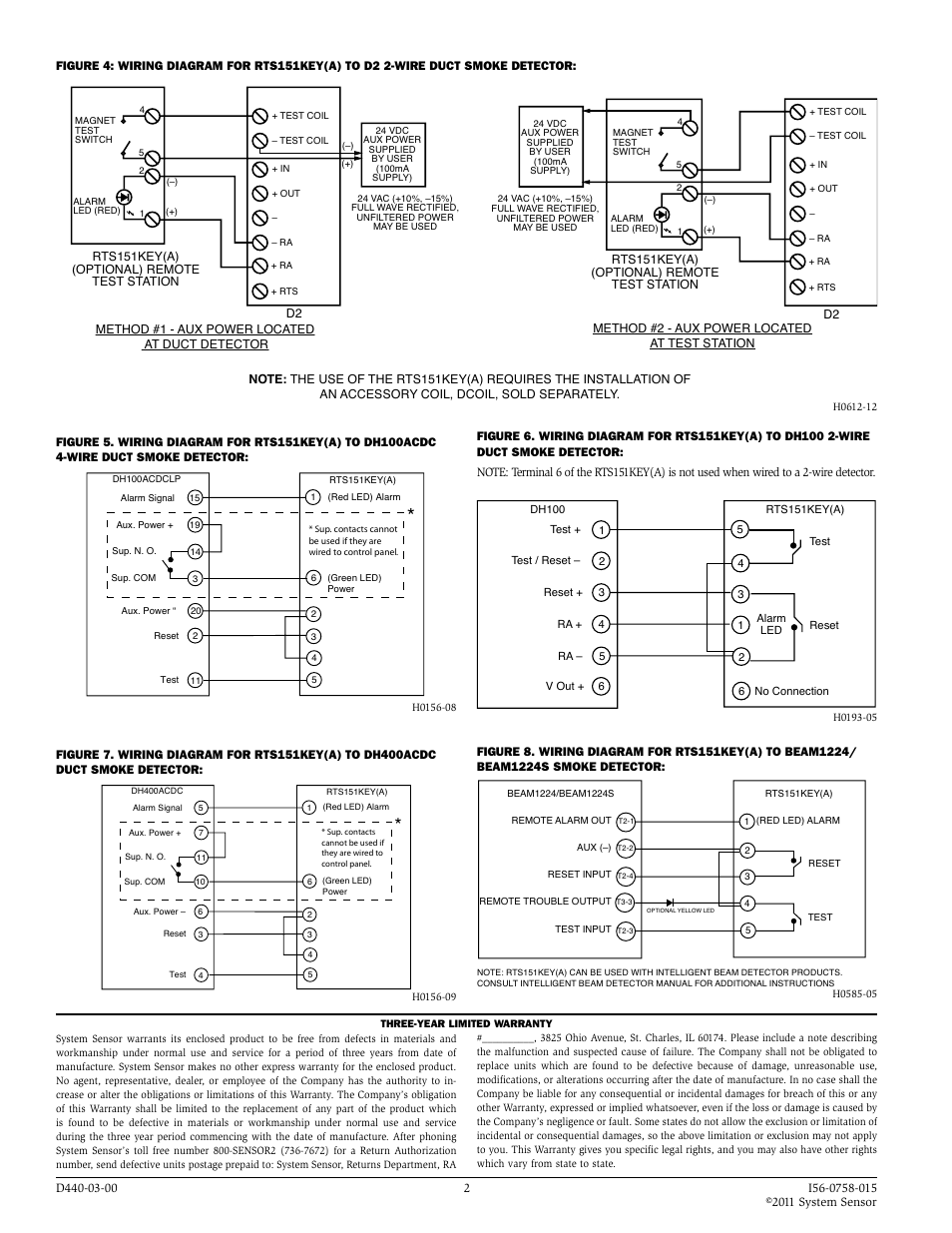
The feature is only available on the d4120 4 wire conventional models. Model d4120 and d4s duct smoke detectors utilize 4 wire photoelectric tech nology for the detection of smoke. Caution do not loop wire under terminals when wiring detectors.
Shipped with each detector for proper application. H0160 00 72 photo detector board 1. Power occurs the damper will fail close.
Duct smoke detector wiring diagram moreover duct detector remote test switch wiring diagram plus simplex duct detector wiring diagram and then ld4p120x duct detector wiring diagram in conjunction with smoke detector wiring diagram as well sie duct detector wiring diagram plus system sensor duct detector wiring diagram in addition smoke detector. Duct smoke detector manufacturers installation instructions. Model d4120 and d4s duct smoke detectors utilize 4 wire photoelectric technology for the detection of smoke.
Supervisory signal h0161 01 reset test power power note. System wiring diagram for duct detectors using a ul listed control panel see figure 8 for wiring of optional accessories. Smoke detectors designed for use in air duct systems are used to sense the presence of smoke in the duct.
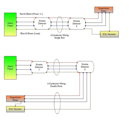
Smoke detectors designed for use in air duct systems are used to sense the presence of smoke in the duct. Smoke introduced into an air duct system will be distributed throughout the entire building. Break wire runs to provide system supervision of connections.
When presence of smoke in the duct is sensed or when loss of. A wiring diagram is a simplified traditional pictorial depiction of an electric circuit.
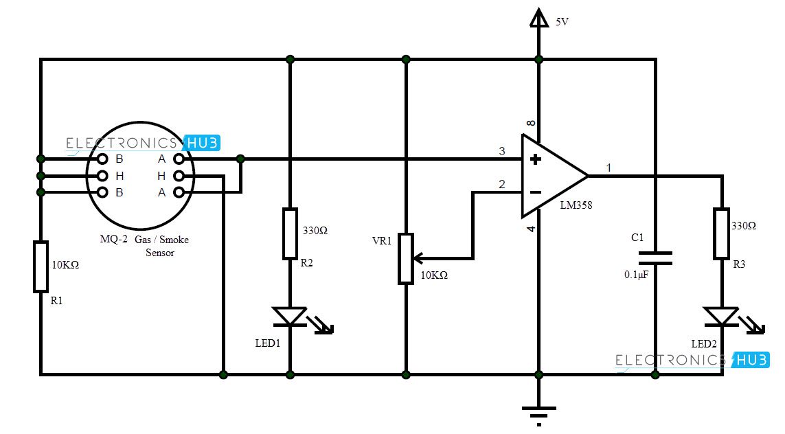 Detector Circuit 1 Wiring Diagram Source
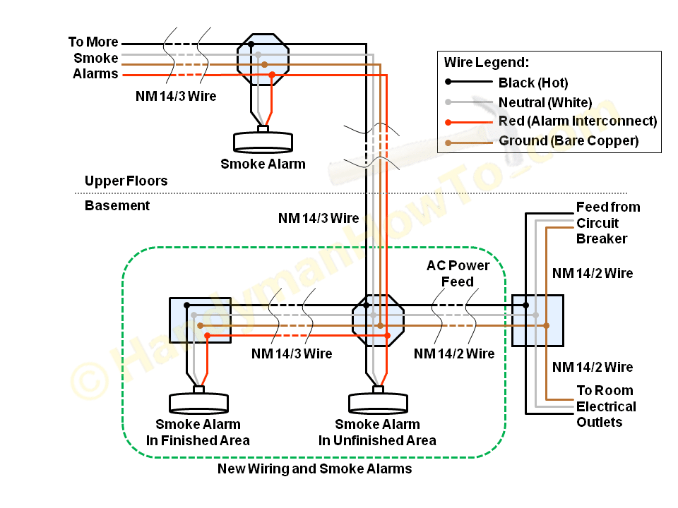
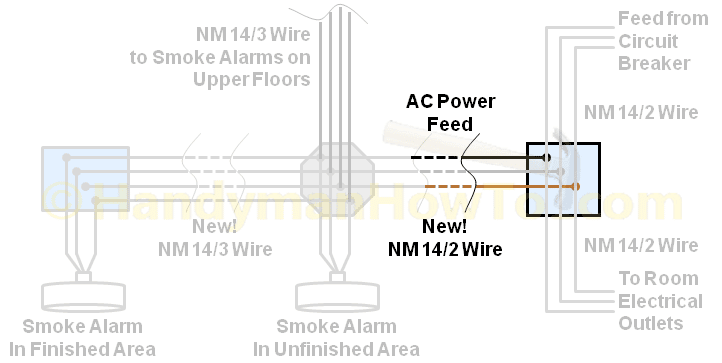
 House Smoke Alarm Wiring Online Wiring Diagram

![]() Acme Transformer Wiring Diagram T181052 Schematic Diagram
Acme Transformer Wiring Diagram T181052 Schematic Diagram


 House Smoke Alarm Wiring Online Wiring Diagram

 Simplex Duct Detector Wiring Diagram Awesome Addressable Smoke
 Addition Fire Simplex Wiring Diagrams On Old 2wire Fan Switch


 Dnr Products System Sensor System Sensor
Smoke Detector Wiring Schematic Online Wiring Diagram

 House Smoke Alarm Wiring Online Wiring Diagram
0 Response to "System Sensor Duct Detector Wiring Diagram"
Post a Comment