Electronic Mouse Killer Circuit Diagram
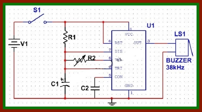
The electronic dog repellent circuit diagram below is a high output ultrasonic transmitter which is primarily intended to. This is insects and mouse repellent circuit using ic556 use high frequency out of the piezo speaker and ic 556 is base as oscillator between 22khz 56khz many electronics circuits and projects for learning in simple ways.
 Electronic Mouse Killer Circuit Diagram Electronic Siren Circuit
Electronic mouse repellent circuit.

Electronic mouse killer circuit diagram. So i developed this mousetrap to catch them alive of course. Their cheapest which will only do one mouse is 20. Copying content to your website is strictly prohibited.
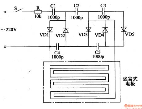
Home circuit diagram automotive circuit electronic mouse killer 1. The low frequency will be sent to control the. The closest equivant commercial product is the victor multi kill electronic mouse trap which costs 100.
When there is a mouse in the certain area ic1s infrared ray will be reflected by the mouse and then receivedand processed by ic1 making ic1s output terminal have low level. Dog repellent project circuit received by email 01282009. The mouse and rat repellent circuit using astable multivibrator which use sound waves or ultrasonic so it escaped away.
Would be appropriate for powering the kill circuit. Electric rat mouse killer. Electronic repellents circuits and projects 11.
By moriszen in home pest control. For power on display of this project. Mousetrap all of a sudden there was a mouse under my roof and once also in my room.
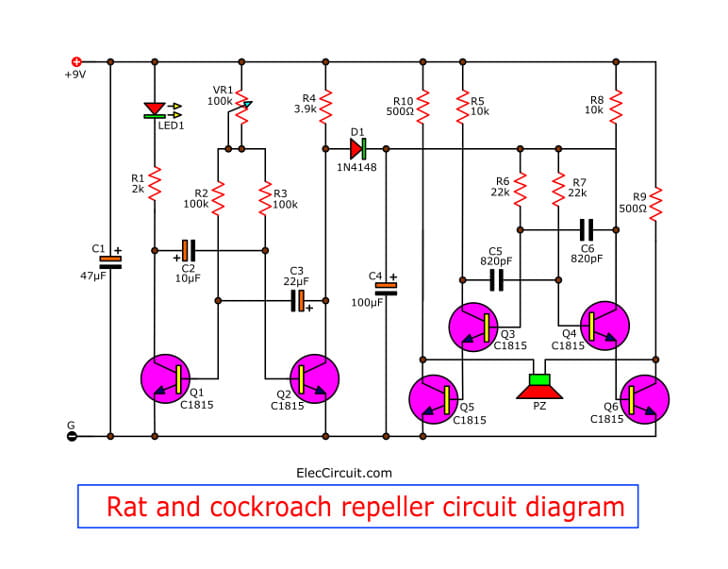
I will install it so that the plexiglas lid has to be closed to make a closed circuit on the input cord that way it will cut down on accidents. Figure 1 rat and cockroach repeller circuit diagram. In this article the admin will share a series of electronic mouse repellent circuit where the mouse are a bully animal that often create chaotic atmosphere the following mouse electromagnetic circuit uses the main component of ic ne 555 and uses several other components.
This electronic mouse repellent circuit was designed because most people agree that rats and mice. And vr 100k will be adjustable of timing range. 4 years ago on introduction.
Pest control circuits schematics or diagrams. This electronic mouse repellent circuit was designed because most people agree that rats and mice are not welcome in our houses meantime some of us dont want to hurt this tiny and beautiful creatures. Use transistor and piezoelectric.

 Ultrasonic Pest Repellers


 Mouse And Rat Repellent Circuit Using Astable Multivibrator

 Pdf Artificial Cell Cell Communication As An Emerging Tool In
Amplidyne Wikipedia
![]() 50 Inspirational Mosquito Repellent Sound Circuit Diagram
50 Inspirational Mosquito Repellent Sound Circuit Diagram
 Ultrasonic Pest Repellers


 Hv Ignition Coil Driver Using 555 Schematic Ham Radio In 2019
 Electronic Mouse Repellent Circuit
 Mosquito Repellent Circuit Koynoypodiwkths Youtube
 Humane Multi Mouse Trap Zapper No Pain Instant Death 4 Steps
0 Response to "Electronic Mouse Killer Circuit Diagram"
Post a Comment