Shear And Moment Diagram Examples
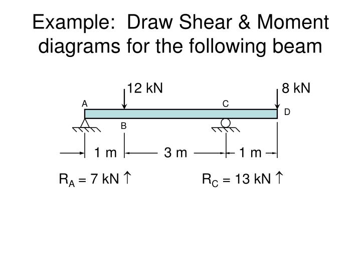
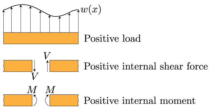
Shear forces occurs when two parallel forces act out of alignment with each other. Shear and bending moment diagrams depict the variation of these quantities along the length of the member.
The discontinuities on the graphs are the exact magnitude of either the external force or external moments that are applied.
Shear and moment diagram examples. Senior academic professional woodruff school of mechanical engineering. Proceeding from one end of the member to the other sections are passed. Module 6 shear force and bending moment diagram examples 602.
After each successive change in loading along the length of the member a fbd. Cut the beam one cut for each beam segment draw a fbd and. Module 5 bending moment diagrams 640.
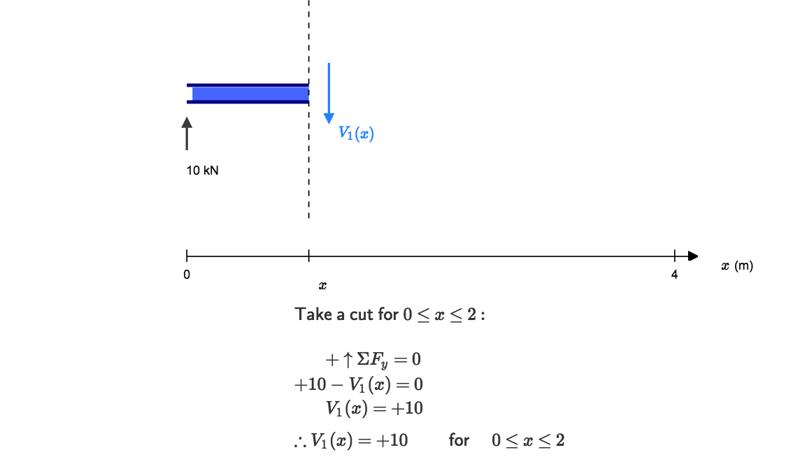
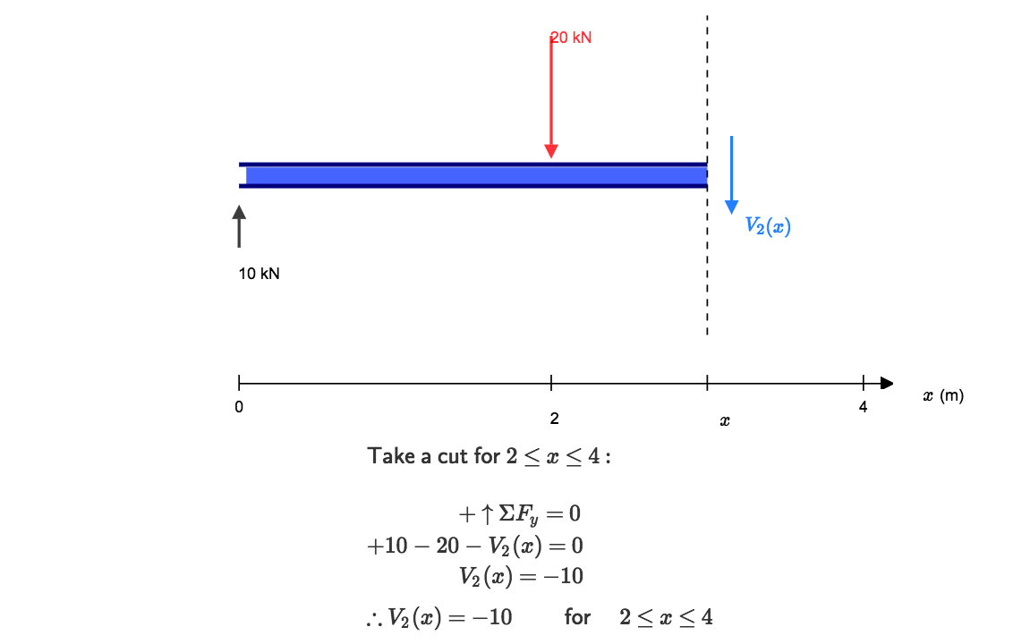
Assume that the beam is cut at point c a distance of x from he left support and the portion of the beam to the right of c be removed. For example at x 10 on the shear force diagram there is a gap between the two equations. Out what to share in the moment is at each of those places.
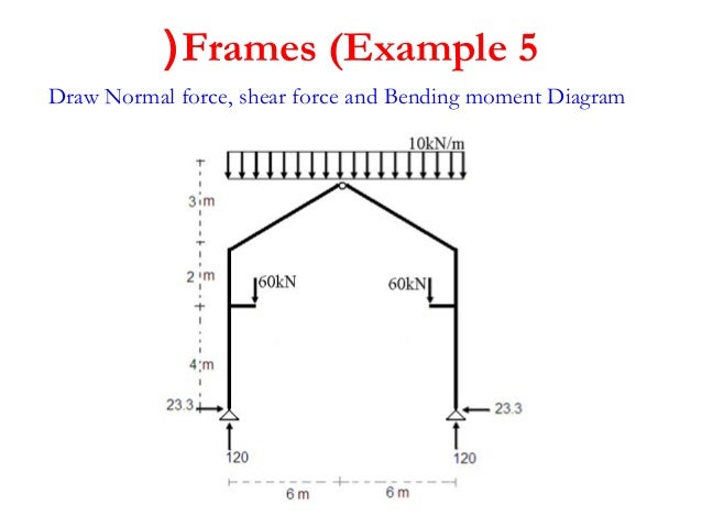
Shear and moment diagrams for frames. Lecture notes cosc321haque 1 pdfc8b shear forces and bending moments in beams shear forces and bending moments in beams reactions shear force diagrams moment diagrams. The beam is loaded with a concentrated moment and a distributed load.
This gap goes from 10 to 153. Identify all information and draw diagram similar to all static or mechanics problems. Another example of drawing shear and moment diagrams graphically for beam.
Draw the shear and moment diagrams for the following frame. Shear and moment diagrams for frames example. Eh c at the roller where we have a value of minus 30000 pound feet.
Notice that the critical values per share is 10000 over minus 10000 over here. In this section we will review sketching shear force and bending moment diagrams. Examples equilibrium method for v and m diagrams semi graphical method for v and m diagrams.
Shear force and bending moment introduction. Relationship between shear force and bending moment. Of both the shear force and the moment anywhere along this beam.
Consider a simple beam shown of length l that carries a uniform load of w nm throughout its length and is held in equilibrium by reactions r1 and r2. The shearing force sf at any section of a beam represents the tendency for. The general steps for shear and moment diagrams are as follows.
In a similar manner it can be seen that if the bending. Lets draw the shear and moment diagram remember to draw the diagram on the compression side of the member. 08 x 768 k ft.
Vx x 416 08 0 416 52ft. Shear and moment diagrams. Construct a free body diagram fbd and solve for all unknown reaction forces.
Civil Engineering Archive November 13 2016 Shear Moment Diagram
 Structural Analysis Ii A60131 Pdf
 Ppt Beams Shear Moment Diagrams Powerpoint Presentation Id 1258447
 4th 2 Lecture Shear And Moment Diagram Structure I
 Shear Force And Bending Moment Diagrams Example 4 Applied Moment
 Mechanics Of Materials Bending Normal Stress Mechanics Of
How To Draw Shear Force Bending Moment Diagram Simply Supported
Shear Force And Bending Moment Diagrams Wikiversity
 How To Calculate Shear Force Diagrams Skyciv
 4th 2 Lecture Shear And Moment Diagram Structure I
Diagram Aplant Number Diagram Inspirational Type Diagram 0d
 How To Calculate Shear Force Diagrams Skyciv
58 Best Pictures Of Triangular Load Shear And Moment Diagram Flow
Shear Moment Diagram Examples Daytonva150
How To Draw Shear Force Bending Moment Diagram Simply Supported
 Statics Ebook Shear Moment And Load Relations
Shear And Moment Diagrams Examples Awesome Solution To Problem 443
How To Draw Shear Force Bending Moment Diagram Simply Supported
Frame Bending Moment Diagram 17 14 Kenmo Lp De
Shear Load And Bending Moment Diagrams
Mechanics Of Materials Chapter 4 Shear And Moment In Beams
 Statics Ebook Shear Moment And Load Relations
 Nptel Mechanical Engineering Strength Of Materials

0 Response to "Shear And Moment Diagram Examples"
Post a Comment