Using The Isothermal Transformation Diagram For An Ironcarbon Alloy Of Eutectoid Composition
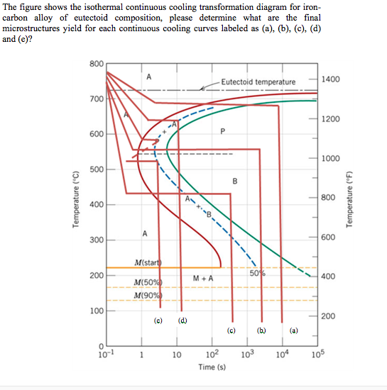
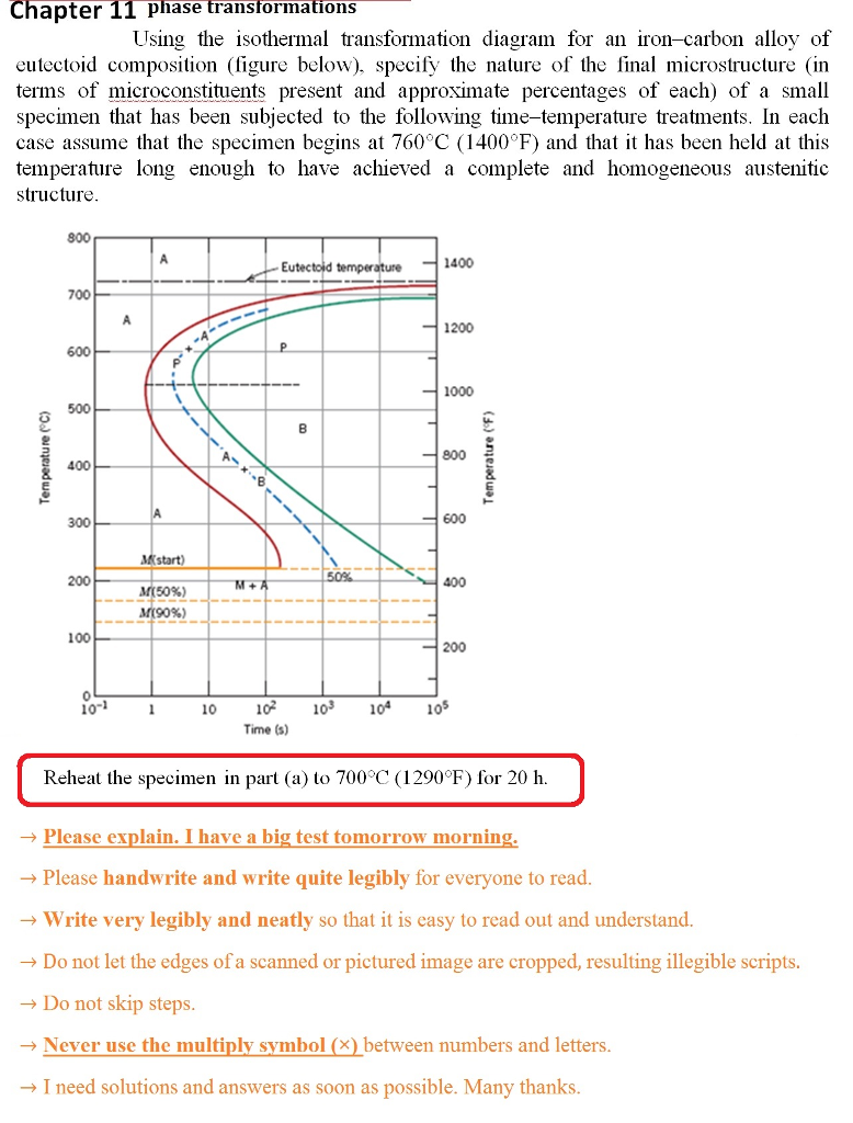
100 79 ratings using the isothermal transformation diagram for an ironcarbon alloy of eutectoid composition figure 1022 specify the nature of the final microstructure in terms of microconstituents present and approximate percentages of each of a small specimen that has been subjected to the following timetemperature treatments. Solution we are called upon to consider the isothermal transformation of an iron carbon alloy of eutectoid composition.
Chapter 10 Phase Transformations
2 rate of transformation.
Using the isothermal transformation diagram for an ironcarbon alloy of eutectoid composition. Figure 1022 specify the nature of the final microstructure in terms of microconstituents present and. Iron carbon phase diagram a review see callister chapter 9. These are the times asked for in the problem statement.
The absolute layer thickness depends on the temperature of the transformation. C particles in ea ferrite matrix diffusion controlled isothermal transf. The ironiron carbide fefe3c phase diagram.
The thickness of the ferrite and cementite layers in pearlite is 81. Using the isothermal transformation diagram for an ironcarbon alloy of eutectoid composition figure 1 specify the nature of the final microstructure in terms of microconstituents present and approximate percentages of each of a small specimen that has been subjected to the following timetemperature treatments. The higher the temperature the thicker the layers.
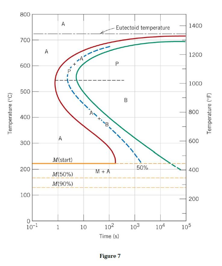
Ttt diagram gives 1 nature and type of transformation. The complete isothermal transformation diagram for an iron carbon alloy of eutectoid composition. In their simplest form steels are alloys of iron fe and carbon c.
Of materials science and engineering 2. 1019 using the isothermal transformation diagram for an iron carbon alloy of eutectoid composition. Approximate percentages of each of a small specimen that has been subjected to the following time.
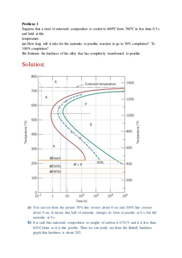
Mse 300 materials laboratory procedures university of tennessee dept. A from figure 1022 a horizontal line at 550 c intersects the 50 and reaction completion curves at about 25 and 6 seconds respectively. 1019 using the isothermal transformation diagram for an ironcarbon alloy of eutectoid composition figure 1022 specify the nature of the final microstructure in terms of microconstituents present and approximate percentages of each of a small specimen that has been subjected to the following timetemperature treatments.
The higher the temperature the thicker the layers. 1018 using the isothermal transformation diagram for an ironcarbon alloy of eutectoid composition figure 1022 specify the nature of the final microstructure in terms of microconstituents present and approximate percentages of each of a small specimen that has been subjected to the following timetemperature treatments. Using the animated figure 1022 the isothermal transformation diagram for an alloy of eutectoid composition specify the nature of the final microstructure in terms of microconstituents present and approximate percentages of each of a small specimen that has been subjected to the following temperature treatments.
2008 基盤創成工学 2008 6 17 材料における相変態 拡散型変態 と組織
Iron Carbon Phase Diagram A Review See Callister Chapter 9
 Transformation Diagram Carbon Schematic Diagram
Chapt 10 Solutions
 Using The Isothermal Transformation Diagram For An Iron Carbon Alloy Of
 Solved Using The Isothermal Transformation Diagram For An
Time Temperature Transformation Ttt Curves
![]() Ppt Phase Transformation Powerpoint Presentation Id 1940682
Ppt Phase Transformation Powerpoint Presentation Id 1940682
Important Terms And Concepts References Questtons And Probtems
9 Iron Carbon Alloys Ferrous Alloys Those Of Which Iron Is The
 Assignment 2 Solutions
 Solved Using The Isothermal Transformation Diagram For An
Applications Of Fe C Phase Diagram
 Solved Using The Isothermal Transformation Diagram For An
 The Atomic Packing Factor Is Defined As The Ratio Of Sphere Volume
 Austenite Wikipedia
 Understanding The Jominy End Quench Test 2015 05 07 Industrial
Chapter 11 Kinetics Microstructure Heat Treating
 2 25 Isothermal Transformation It Diagrams For A Eutectoid Steel
 Using The Isothermal Transformation Diagram For An Chegg Com
Time Temperature Transformation Ttt Curves
![]() Solved Using The Isothermal Transformation Diagram For An Iron
Solved Using The Isothermal Transformation Diagram For An Iron
Engineering Materials
Isothermal Transformation Diagrams
0 Response to "Using The Isothermal Transformation Diagram For An Ironcarbon Alloy Of Eutectoid Composition"
Post a Comment