Logical Vs Physical Network Diagram
A physical layoutmap usually involves a diagram of the actual floor the way it would be seen if you were on the. Logical vs physical logical vs physical network diagram physical topology of a.
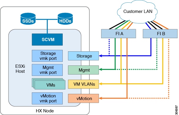 Cisco Hyperflex Systems Network And External Storage Management
Networks that use vlans or vpns often have radical differences between their logical topologies and their physical topologies.
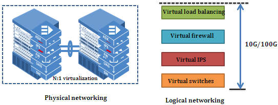
Logical vs physical network diagram. The potentials of the network access devices and media decides the physical topology of a network. In most cases the logical network is a simple class c network such as 19216800 with the default subnetmask of 2552552550. So while any data flow diagram maps out the flow of information for a process or system the logical diagram provides the what and the physical provides the how.
A logical dfd focuses on the business and business activities while a physical dfd looks at how a system is implemented. A physical network diagram shows the physical connections of network components while a logical one shows how they relate and communicate with each other. See ethernet and logical vs.
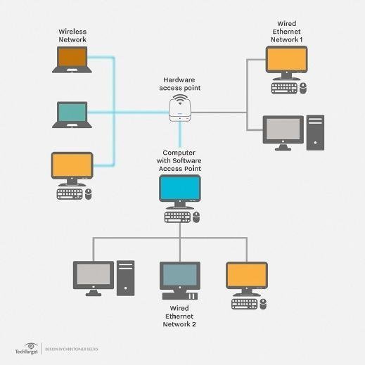
The difference between logical and physical network design abstract connecting computers together to create a network greatly increases the communication capabilities and can even save a company substantial amounts of time and money. The logical diagram that shows four computers in this case would reflect only a single computer in a physical diagram. Most strong network designs require a sophisticated yet robust physical network diagram and a sensible logical network diagram.
Back to list top. Physical vs logical topology. At the same time the logical topology indicates how data is managed in the network irrespective of its physical topology.
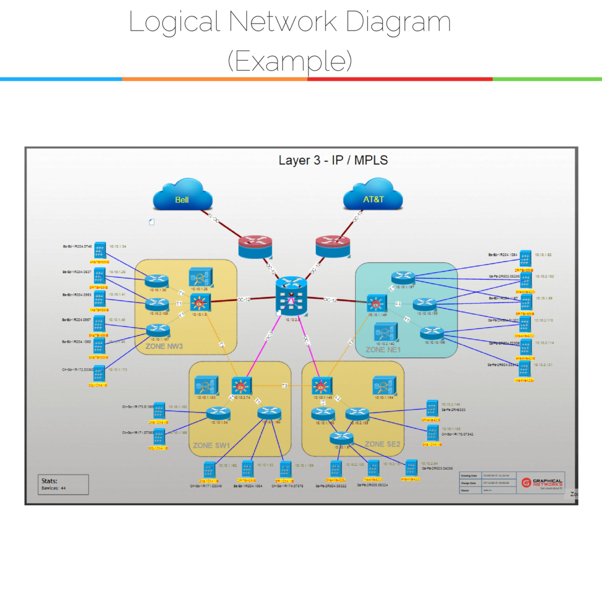
The physical network diagram is used when one needs to visualize the physical network structure of any organization where as the logical network diagram would be used only to know protocols for the data movement within a network. The difference between physical and logical topology is present and can be demonstrated in a shared ethernet network that employs hubs instead of switches. However its physical topology is a star in which every node on the network connects to a central hub.
A logical network layout clearly shows the ip addresses associated with each part of the network. With this type of connection the logical topology looks as if each node is connected into the same bus.
 Schematics Of The Logical And Physical Networks Of The Io Link
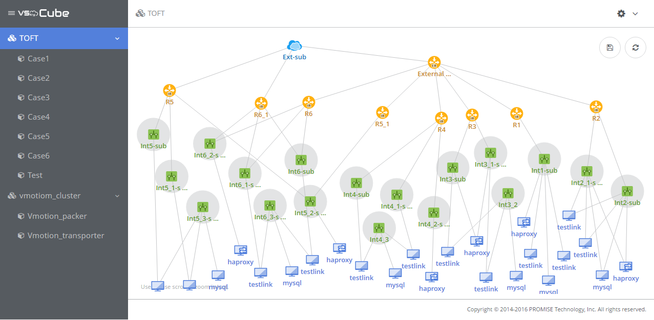 Promise Technology Storage Solutions For It Cloud Surveillance


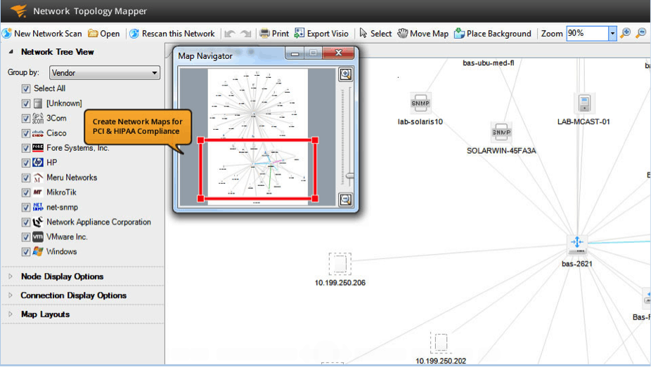 Network Diagram Software Solarwinds Network Topology Mapper Review
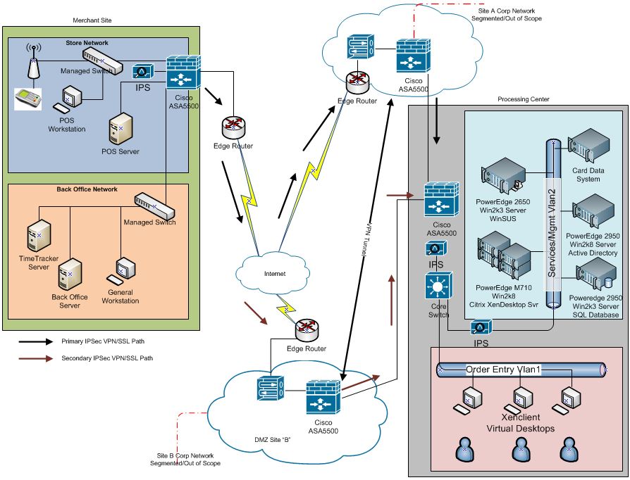 Pci Dss And The Network Diagram Optiv
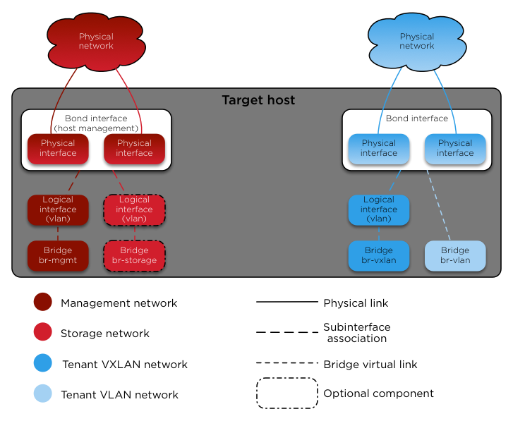 Configuring The Network Openstack Ansible 13 3 12 Documentation


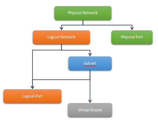 2 1 Quick Understand On Vlcp Network Concepts Vlcp 1 3 0
 Physical Vs Logical Diagram Wiring Diagram Schematics
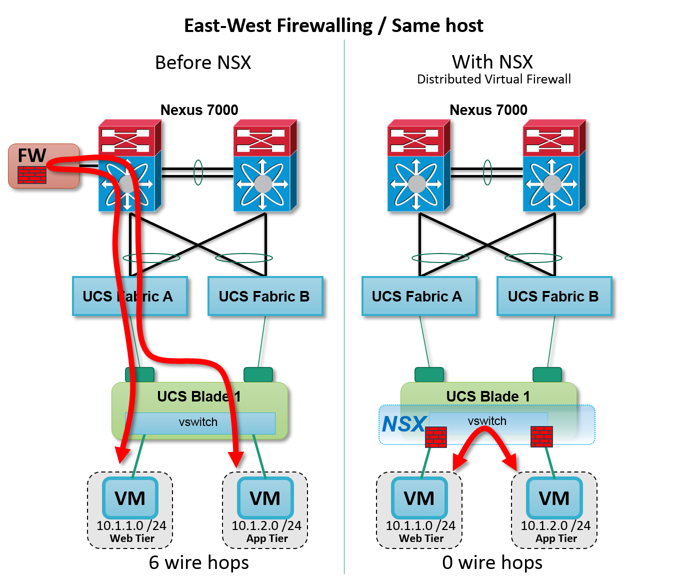
 Structural Design Considerations For Data Center Networks
 Azure Network Security Blogg Microsoft Azure

 Logical And Physical View Of Trusted Virtual Domains Tvds


 Data Flows Common Dfd Mistakes 146881654623 Data Flow Diagram Vs
0 Response to "Logical Vs Physical Network Diagram"
Post a Comment