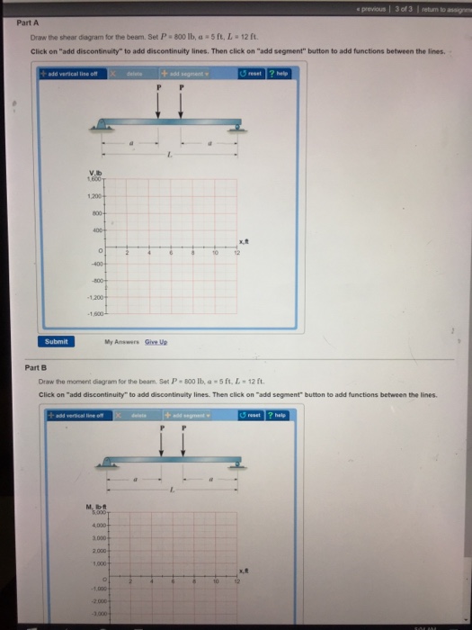
Draw The Shear Diagram For The Beam Set P 800 Lb A 5 Ft L 12 Ft
To draw the shear diagram. B set p800lb a5ft l12ft.
 Patent Us 9 182 596 B2
1 answer to draw the shear and bending moment diagrams for the beam.
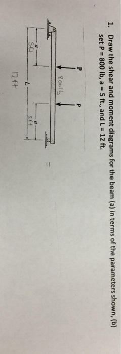
Draw the shear diagram for the beam set p 800 lb a 5 ft l 12 ft. Vbc 2400 800x is linear. Show transcribed image text draw the shear diagram for the beam. Draw the shear and moment diagrams for the beam a in termsof the parameters shown.
Draw the shear and moment diagrams for the cantilevered beam. This is the line for zero shear. A in terms of the parameters shown.
800 lb of shear force is uniformly distributed along segment ab. Click on add discontinuity to add discontinuity lines. Draw the shear and moment diagrams for the following beam 12 ft.
The beam consists of two segments pin connected at b. Set p 800 lb a 5 ft l 12 ft. B set p 800lb a 5ft.
In this case 2 lbft. Draw the shear and moment diagrams for the beam a in termsof the parameters shown. If l 10 ft the shaft will fail when the maximum moment is m max 5 kip ft.
Shear and moment diagrams draw the shear and moment diagrams for the following beam 10 ft. Draw the shear and moment diagrams for the beam. Determine the largest uniform distributed load w the shaft will support.
C a b 5 ft 100 lb 800 lb ft 5 ft prob. I like to draw my shear diagrams directly below the actual member so that they line up and i designate my shear diagrams with a big v. 8 ft 4 ft 6 ft 700 lb 150 lbft 800 lb и ft a b c 7 solutions 44918 12709 1039 am page 626 83.
60 k 8 ft. At x 2 ft vbc 800 lb. Following beam l l l p p a b shear and moment diagrams.
At x 6 ft vbc 2400 lb. Shear diagrams are an easy way to visualize shear values along a beam or member and also reveal the maximum positive and negative shear values. When vbc 0 2400 800x 0 thus x 3 ft or vbc 0 at 1 ft from b.
Then click on add segment button to add functions between the lines. The shaft is supported by a thrust bearing at a and a journal bearing at b.
 Hibbeler Statics Solution Chapter 7 1
 Hibbeler Statics Solution Chapter 7 1
 Construction Incidents Investigation Engineering Reports March 4
 Ch 12 Static Equilibrium Elasticity

329 6 1 Draw The Shear And Moment Diagrams For The Shaft The
Engineering Mechanics Statics
 Structure Magazine A Practical Design For Thin Composite Steel
 In Situ Analytical Techniques For Battery Interface Analysis
 Trawling Gear In California
Solution
Mechanics Of Materials Chapter 5 Stresses In Beams

Book Solution Mechanics Of Materials Russell C Hibbeler S C
 Chapter 06
Untitled
Solution
329 6 1 Draw The Shear And Moment Diagrams For The Shaft The
Untitled
0 Response to "Draw The Shear Diagram For The Beam Set P 800 Lb A 5 Ft L 12 Ft"
Post a Comment