Atwood Machine Free Body Diagram
An atwood machine is a basic physics laboratory device often used to demonstrate basic principles of dynamics and acceleration. Atwoods machine is the name of a device that looks like this.

It is not a practical machine.
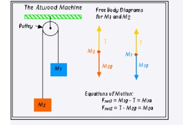
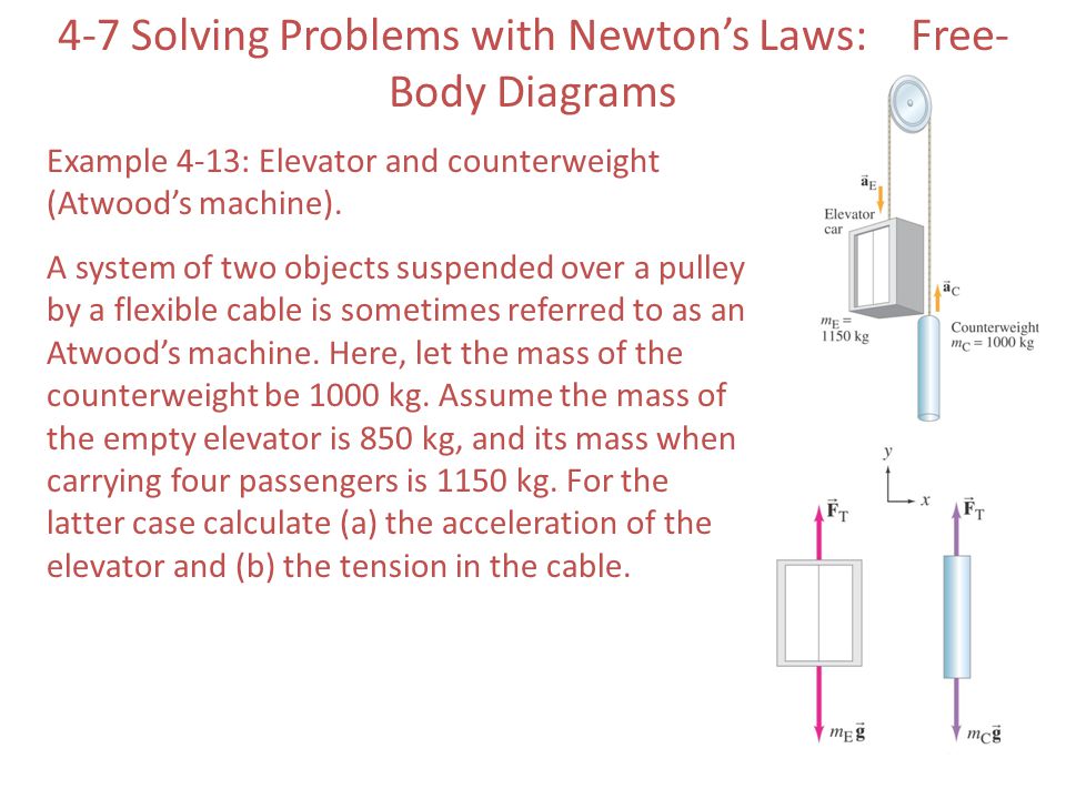
Atwood machine free body diagram. On a piece of paper draw two free body diagrams. There are two free body diagrams since there are two masses. Our sign convention depicted by the acceleration vectors is that m 1 accelerates downward and that m 2 accelerates upward as would be the case if m 1 m 2.
Assume m 2 is larger than m 1. The problem solving approach will be the same. The atwoods machine is used below to help in understanding how newtons 2nd law applies to a system of two connected masses.
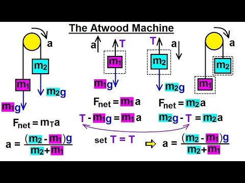
Apply newtons 2nd law to an atwoods machine and derive a formula for the expected acceleration in terms of m 1 and m 2. Since you already have a picture of the atwoods machine i will draw two free body force diagrams. Then you can create free body diagrams for both object m 1 and m 2 as shown below.
A simple atwood machine consists of two masses m 1 and m 2 that are connected by a string wound over a pulley as seen in the figure below. Free body diagrams 2 of 10 the atwood machine michel van. The machine typically involves a pulley a string and a system of masses.
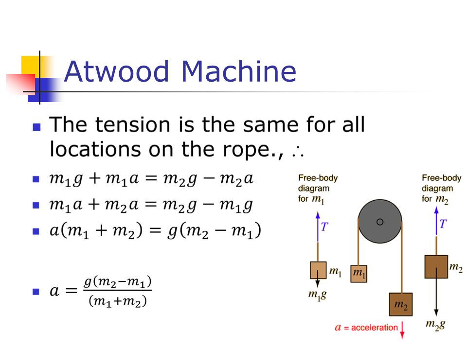
T is the tension in the string assumed to be the same for both masses. The diagram at right shows an atwood machine along with a free body diagram for each mass and the resulting equations of motion. The instructions following that diagram will help you find the theoretical equations for a y.
This is a good assumption as long as it is a single strand of string and a relatively light pulley system. Using this diagram write newtons. Each object is experiencing a downward force of gravity.
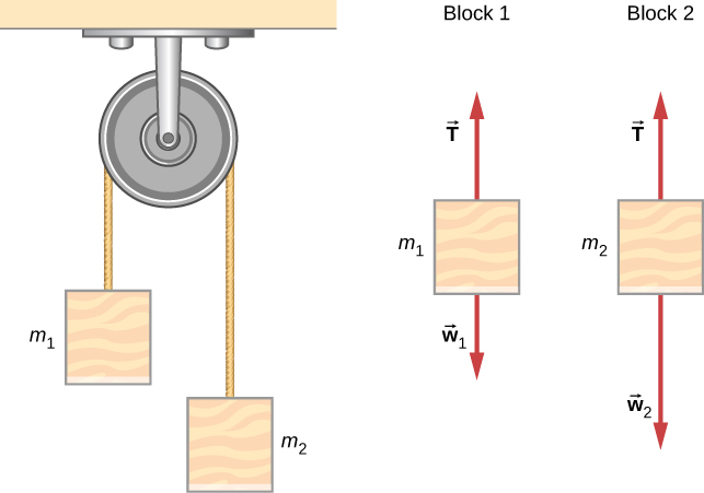
One for each of the masses showing all forces acting on each mass. Suppose two different masses m 1 and m 2 are attached to a rope which is placed over a pulley as indicated in the diagram below. The free body diagrams of the two hanging masses of the atwood machine.
The final example problem will be a case of a modified atwoods machine with the surface inclined as shown below. Newtons second law atwoods machine theory the free body diagrams below show the forces acting on each of the masses. The ideal atwood machine consists of two masses m 1 and m 2 connected by a massless inelastic string which passes over a frictionless pulley.
Motion in the upward direction is positive. Start by making a free body diagram in the box below. In this video i will show the traditional and the free body diagram methods of finding.
The free body diagrams for each individual mass are shown below.
 Solved The Device Shown Below Is The Atwood S Machine Consider
 How To Solve An Atwood Machine Problem With Friction Quora

 Physics Mechanics Free Body Diagrams 2 Of 10 The Atwood Machine
 Physics Interactive Notebook Notes Atwood Machine By Iteach Science
Physical System Used By Mcdermott Shaffer And Somers A Original

 6 1 Solving Problems With Newton S Laws University Physics Volume 1
 Atwood Machine Diagram Sembilan Stanito Com
 Physics Ufpm Challenge Atwood Machine
 Homework And Exercises Tension In An Atwoods Machine Conceptual

 Chapter 5 Two Dimensional Forces Equilibrium An Object Either At

 Giancoli 4 1 23 Normal Force With Atwood Machine Video Dailymotion
 How To Solve A Physics Problem Undergrads Usually Get Wrong Wired
0 Response to "Atwood Machine Free Body Diagram"
Post a Comment