D Flip Flop State Diagram
The clock has to be high for the inputs to get active. On this channel you can get education and knowledge for general issues and topics.

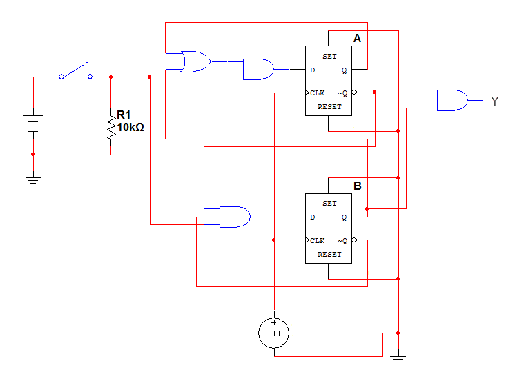
D flip flop is simpler in terms of wiring connection compared to jk flip flop.

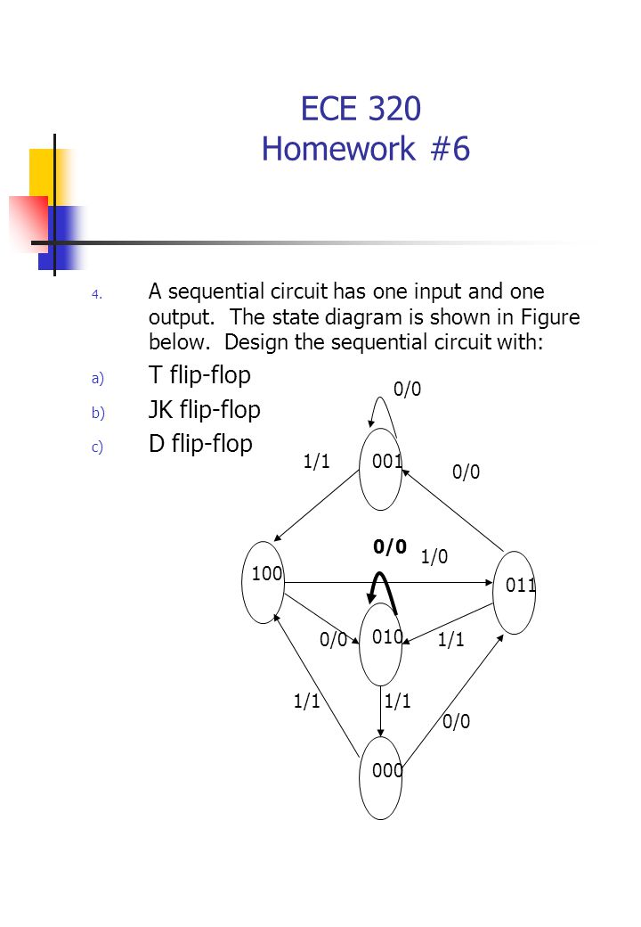
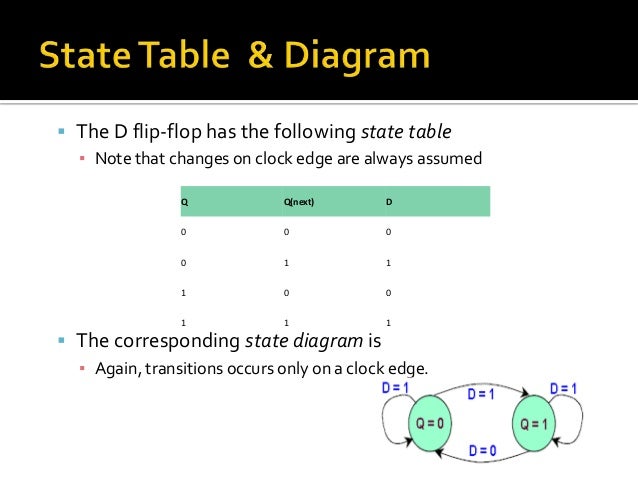
D flip flop state diagram. Whenever the clock signal is low the input is never going to affect the output state. The truth table and logic diagram is shown below. Draw a state diagram 3.
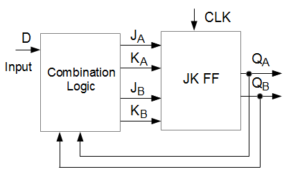
It can have only two states either the state 1 or 0. We attach a combinational circuit to a d flip flop to convert it into jk flip flop. The general block diagram represents a flip flop that has one or more inputs and two outputs.
Assign state number for each state 4. A flip flop is a type of circuit that contains twostates and are often used to store stateinformation by sending a signal to the flip flop the state canbe changed flip flops are used in a number ofelectronics including computers andcommunications equipment there were a number. Thus d flip flop is a controlled bi stable latch where the clock signal is the control signal.
It can also be used for counting of pulses and for synchronizing variably timed input signals to some reference timing signal. Read input while clock is 1 change output when the clock goes. Similarly when q0 and q1the flip flop is said to be in clear state.
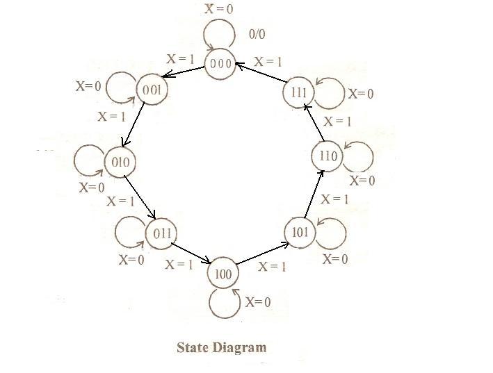
Flip flops can be constructed by using nand and nor gates. Flip flop electronics when used in a finite state machine the output and next state depend not only on its current input but also on its current state and hence previous inputs. In this diagram a state is represented by a circle and the transition between states is indicated by directed lines or arcs connecting the circles.
Jk flip flop is modified version of d flip flop. Derive input equations 5. Draw state table 5.
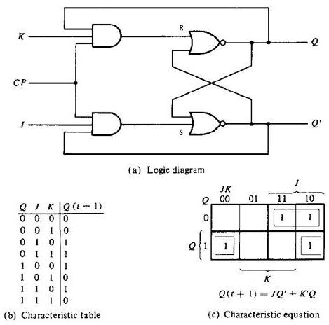
Edge triggered flip flop contrast to pulse triggered sr flip flop pulse triggered. In the previous article we discussed rs and d flip flopsnow well lrean about the other two types of flip flops starting with jk flip flop and its diagram. Its state table is given below.
Similarly a flip flop with two nand gates can be formed. In addition to graphical symbols tables or equations flip flops can also be represented graphically by a state diagram. Flip flops state tables diagrams.
A flip flop is also known as bit stable multi vibrator. The flip flop consists of two useful states the set and the clear statewhen q1 and q0 the flip flop is said to be in set state. One d flip flop for each state bit.
Final Exams Review
Circuit State Diagram State Table G Circuits With Flip Flop
Ece 223 Solutions For Assignment 6
 D Flip Flop State Diagram Lovely Solved A Sequential Circuit Has E
 Flip Flop Diagram Qvr Rakanzleiberlin De
 Ece 320 Homework 6 Derive The State Table And State Diagram Of The
Ece 223 Solutions For Assignment 6
 Summary Of The Types Of Flip Flop Behaviour

 Gallery Logic Diagram For D Flip Flop Using A Block The Rs Flipflop

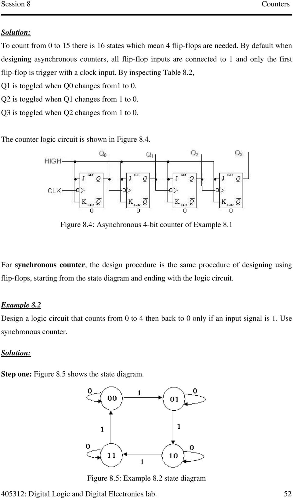 To Design Digital Counter Circuits Using Jk Flip Flop To Implement
 Flip Flop S State Tables Diagrams

 Finite State Machines Sequential Circuits Electronics Textbook

 Solved Draw The State Diagram Of The Elevator Controller

 What Is State Diagram Of Moore Of 101 Sequence Detector With One Bit
Whenever the clock signal is low the input is never going to affect the output state.
ReplyDeleteThe clock has to be high for the inputs to get active.
ReplyDeletevisit link my websiteTel-U