Block Diagram Transfer Function Solver
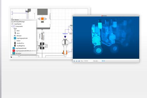
Build and analyze control systems document design decisions and interactively evaluate controllersall in one system with one integrated workflow. Block diagram simplification rules equivalents.
 Control Theory Wikipedia
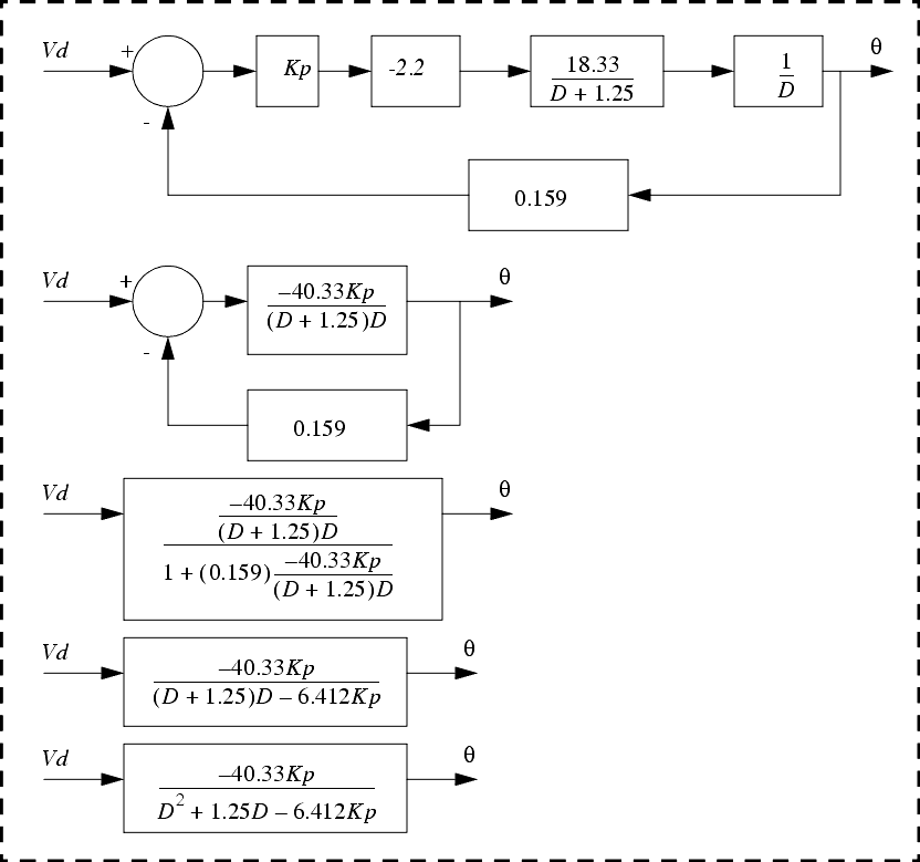
The final equation is θ sb s d sa s θr sθ s which you can solve for both of the requested transfer functions.
Block diagram transfer function solver. Obviously the block diagram of this example can be generalized to represent any system with a rational transfer function. This provides a pictorial view of a control system. A conventional way of representing linear time invariant systems is via block diagrams.
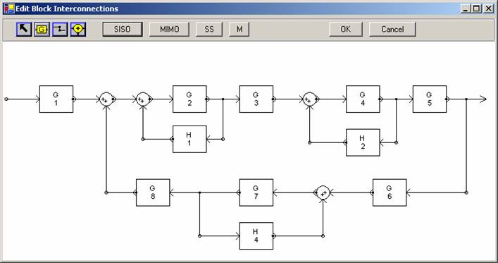
You can edit this block diagram using creately diagramming tool and include in your reportpresentationwebsite. Block diagrams are considered in section 22. 2 associative and commutative properties rule.
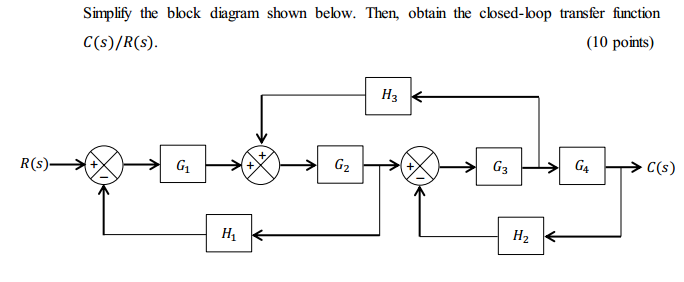
Home solved problems process control rule1. The first step in creating a transfer function is to convert each term of a differential equation with a laplace transform as shown in the table of laplace transforms. Step 3 get the overall transfer function by adding all those transfer functions.
Derive transfer function from block diagrams 2 feeit exam. Block diagram algebra is introduced in section 23 as a suitable tool for obtaining transfer functions of systems whose block diagrams are known. Step 2 repeat step 1 for remaining inputs.
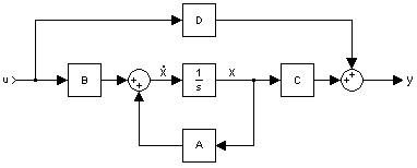
If can be separated into several terms by long division which can be individually implemented and then combined to generate the overall output. 3 distributive property rule. The relationship from an input signal u to an output signal y in the laplace transform domain.
A block diagram showing calculator. Transfer functions in block diagrams. Ly gs lublock diagram form.
Underlying the wolfram control systems solution is a powerful hybrid symbolic numeric computation engine with numerics of any precision high performance symbolics. Faster than a calculator. Example problem on how to derive closed loop transfer function from block diagram.
Instead you need to close the loop by making the replacement e sθr sθ s and then solve for the two transfer functions you are asked for. 4 blocks in parallel rule. 6 negative feedback loop equivalent.
A transfer function g s relates an input u s to an output y s. Step 1 find the transfer function of block diagram by considering one input at a time and make the remaining inputs as zero. 5 positive feedback loop rule.
![]() Transfer Function Block Diagram Solver Best Of Control Systems Quick
Transfer Function Block Diagram Solver Best Of Control Systems Quick
Toolbox 3 3 1


 Control Systems Feedback Loops Wikibooks Open Books For An Open World
 Block Diagram Solver Wiring Diagrams Simple
Transfer Function Block Diagram Solver Inspirational Chemical
 Closed Loop System And Closed Loop Control Systems
 Transfer Functions In Simulink Part 1 Creating And Using Transfer
 Open Loop System And Open Loop Control Systems
 Block Diagram Transfer Function Schematic Diagram
![]() Block Diagram Transfer Function Reduction Block Wiring Diagram
Block Diagram Transfer Function Reduction Block Wiring Diagram
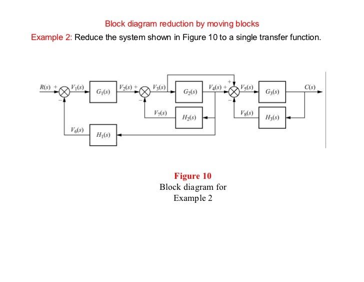 Reduction Of Multiple Subsystem Compatibility Mode
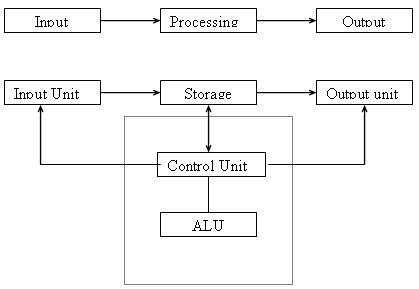
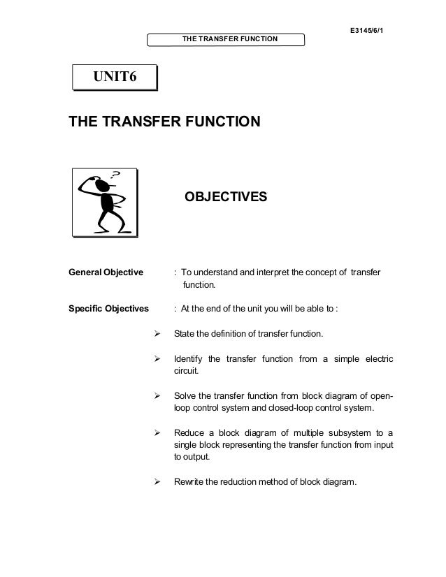 Basic Control System Unit6
Block Diagram Reduction Technique Rules Ppt Michaelhannan Co
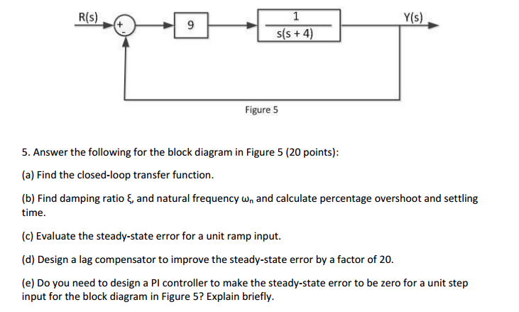 Solved Answer The Following For The Block Diagram In Figu
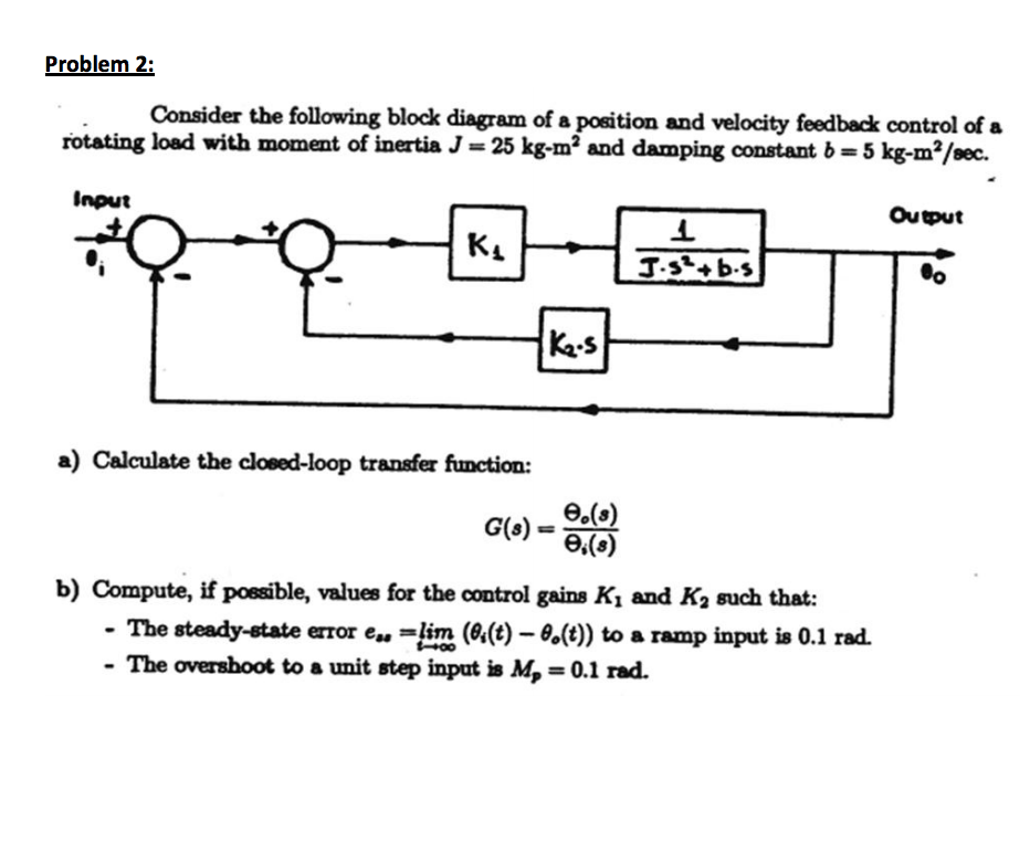 Solved Consider The Following Block Diagram Of A Position
 Transfer Function Solving A Block Diagram Problem Of An Lti System
Wolfram And Mathematica Solutions For Control Systems
0 Response to "Block Diagram Transfer Function Solver"
Post a Comment