Phase Lock Loop Block Diagram
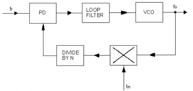
The figure shows the block diagram of the phase locked loop system in fm transmitter that consists of different blocks such as a crystal oscillator phase detector loop filter voltage controlled oscillator vco and frequency divider. Basics of phase lock loop 3.
 Vco15 10 Phase Locked Loop Fundamentals
6 cd4046b phase locked loop.
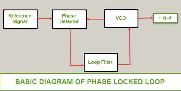
Phase lock loop block diagram. Block diagram of phase lock loop 5. A phase locked loop consist of a phase detector and a voltage controlled oscillator. The pll forms the basis of a number of rf systems including the indirect frequency synthesizer a form of fm demodulator and it enables the recovery of a stable continuous carrier from a pulse waveform.
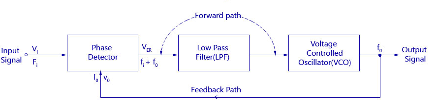
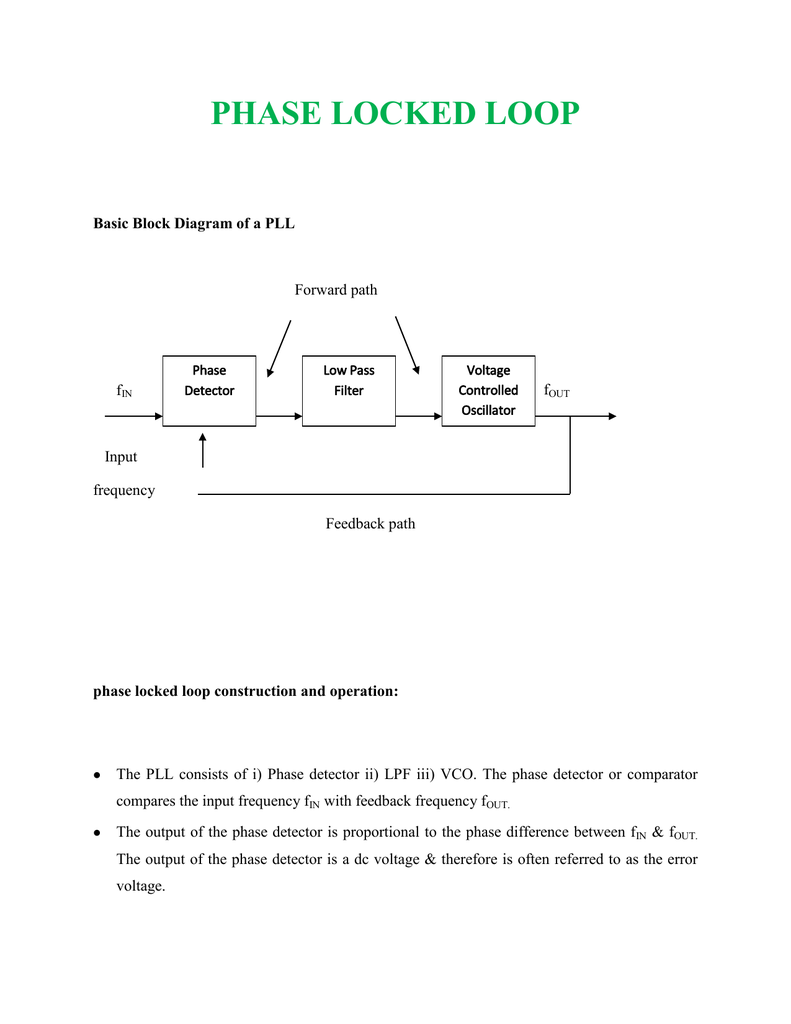
Basic block diagram of a pll. In this video i have explained phase lock loop by following outlines. Figure 1 shows a simplified block diagram of the major components in a pll.
A phase locked loop or phase lock loop pll is a control system that generates an output signal whose phase is related to the phase of an input signal. The simplest is an electronic circuit consisting of a variable frequency oscillator and a phase detector in a feedback loop. The output of the phase detector is the input of the voltage controlled oscillator vco and the output of the vco is connected to one of the inputs of phase detector which is shown below in the basic block diagram.
The concept of phase locked loops pll first emerged in the early 1930sbut the technology was not developed as it now the cost factor for developing this technology was very high. Phase lock loop 2. Lpf controls the characteristics of the phase locked loop.
Phase lock loop basics block diagram working in communication engineering by. Phase locked loops pll introduction to pll. Need of phase lock loop 4.
Frequency continuous to change until it equals the input frequency and the pll is in phase lock mode. It is the most important part of the phase locked loop system. The phase locked loop pll is a very useful building block particularly for radio frequency applications.
This phase locked loop tutorial gives all the basics required for an understanding of pll technology. A versatile building block for micropower digital and analog applications phase comparator i is an exclusive or network that operates analogously to an overdriven balanced mixer. A phase locked loop pll is a closed loop frequency control system based on the phase difference between the input clock signal and the feedback clock signal of a controlled oscillator.
When phase locked the loop tracks any change in the input frequency through its. There are several different types. Ie capture range lock ranges bandwidth.
Phase locked loop.
 Phase Locked Loop Operating Principle And Applications

 Yeh Group Scso Phase Locked Loop

 Phase Lock Loop Block Diagram 8 Download Scientific Diagram
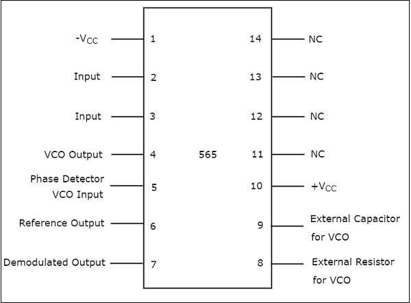
 Phase Lock Loop Pll Lm565 Circuit

 Basics Of Phase Locked Loop Techniques Chapter 4 Synchronization
 Phase Locked Loop
 Linear Integrated Circuits Applications Phase Locked Loop Ic
 Phase Locked Loop Operating Principle And Applications
![]() Phase Locked Loops For High Frequency Receivers And Transmitters
Phase Locked Loops For High Frequency Receivers And Transmitters
 50 Ghz Phase Locked Loop Block Diagram Download Scientific Diagram
 Principle Block Diagram Of Phase Locked Loop Download Scientific
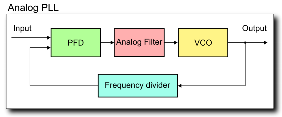 File Analog Pll Block Diagram Png Wikimedia Commons
 Phase Locked Loop Block Diagram Download Scientific Diagram
Phase Locked Loop
 Pll Phase Locked Loop How It Works Electronics Notes
0 Response to "Phase Lock Loop Block Diagram"
Post a Comment