Consider The Circuit In The Diagram
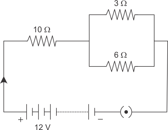
Consider the circuit diagram here. Consider the circuit in the diagram below in which r 14 ω.
Please Solve The Problem For Me Electricity Science Class 10
B find the potential difference across the 3 ω resistor.

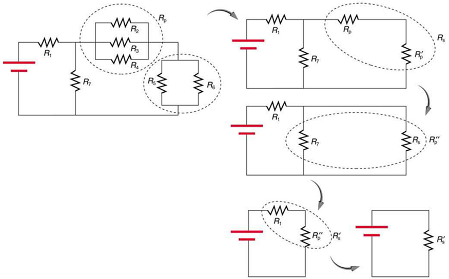
Consider the circuit in the diagram. A find the equivalent resistance of all the resistors combined in this circuit. Consider the arrangement shown in the diagram. As an illustration of the use of electrical symbols in schematic diagrams consider the following two examples.
180 v v r 4 400 r 1 200 r 2 300 3 100 label the voltage v 180 v and the resistors starting in the upper left r 1 200 r 2 300 r 3 100 and r 4 400. Consider the circuit shown in the diagram below for r1 5 ω r2 8 ω r3 8 ω r4 8 ω and v0 80 v. Using the verbal description one can acquire a mental picture of the circuit being described.
This is because the electric potential between two points is independent of the path that current needs to take to complete the circuit. When the bar is at position x what is the magnetic flux through the closed circuit. To nd the total current through the circuit we compute its equivalent resistance.
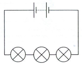
Three d cells are placed in a battery pack to power a circuit containing three light bulbs. If this was a. If an answer is a direction up down left right in or out give an explanation justifying your answer.
Physics problem circuits help. Yes you are definitely on the right track. Let r1 20 ohm r2 3 ohm and r3 10 ohm.
When hooked up to a certain battery there will be a current i moving to the right in the top wire above resistor a. Right now it looks like you have calculated the circuit current current through the battery. I14 2424 14990.
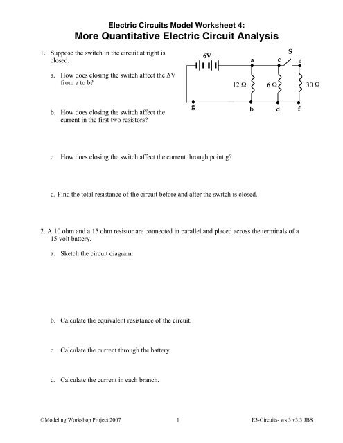
Consider the circuit shown. Express all of your quantitative answers in terms of some or all of w x v andor b only. B firstly we know the voltage across two parallel branches is the same.
A conducting bar slides along a u shaped conducting r. We include additional resistors representing the resistance of the wire and then treat the wires in the diagram as ideal wires. A find the current flowing through the 5 ω resistor.
Calculate the power delivered to each resistor in the circuit shown in figure p2131. Consider the following circuit diagram. Consider the circuit in the diagram below in which r 14 ω.
The current in the parallel circuit will divide in inverse proportion to the resistance in each branch. Calculate the current through r4.
 Resistors In Series And Parallel College Physics
 Kirchhoff S Rules Multi Loop Direct Current Circuits
 Consider The Following Circuit Diagram If R1 R2 R3 R4 R5 3a Find
 How Electrical Circuits Work Lighting Basics Bulbs Com
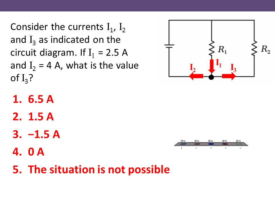
 3 Consider The Circuit B
 Chapter 25 Electric Circuits Ppt Video Online Download
 When Choosing Bjt Or Mosfet We Need To Consider Power Level Drive


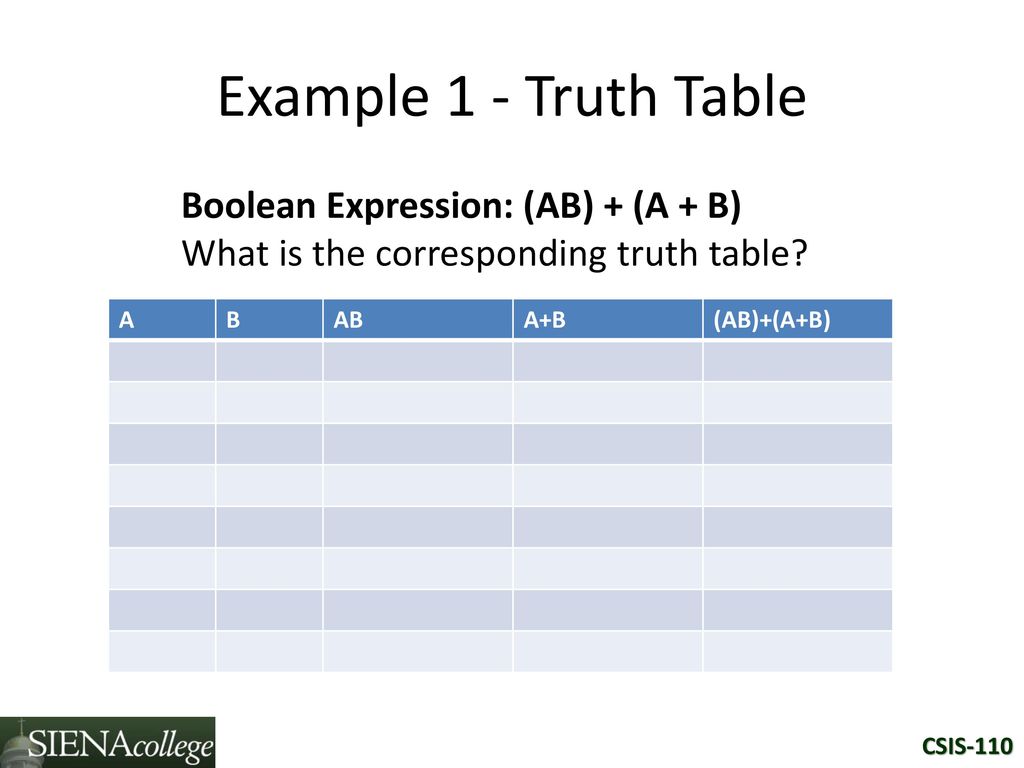 Csis 110 Introduction To Computer Science Ppt Download
Gate2006 35 Gate Overflow
 Filter Amplifier In Cardiac Pulse Meter Electrical Engineering
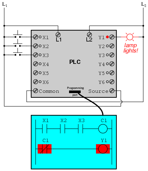 Programmable Logic Controllers Plc Ladder Logic Electronics
 Thevenins Theorem Tutorial For Dc Circuits
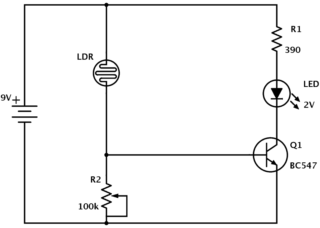 Ldr Circuit Diagram Build Electronic Circuits
0 Response to "Consider The Circuit In The Diagram"
Post a Comment