Using The Isothermal Transformation Diagram
Phase diagram phase transformations ent 145 materials engineering chapter 10 phase transformations. Were looking at the temperature on the y axis.
Phase Transformations Kinetics We Need To Consider The Time
These are the times asked for in the problem statement.
Using the isothermal transformation diagram. Mse 300 materials laboratory procedures university of tennessee dept. Ttt diagram gives 1 nature and type of transformation. It is also called isothermal transformation diagram definition.
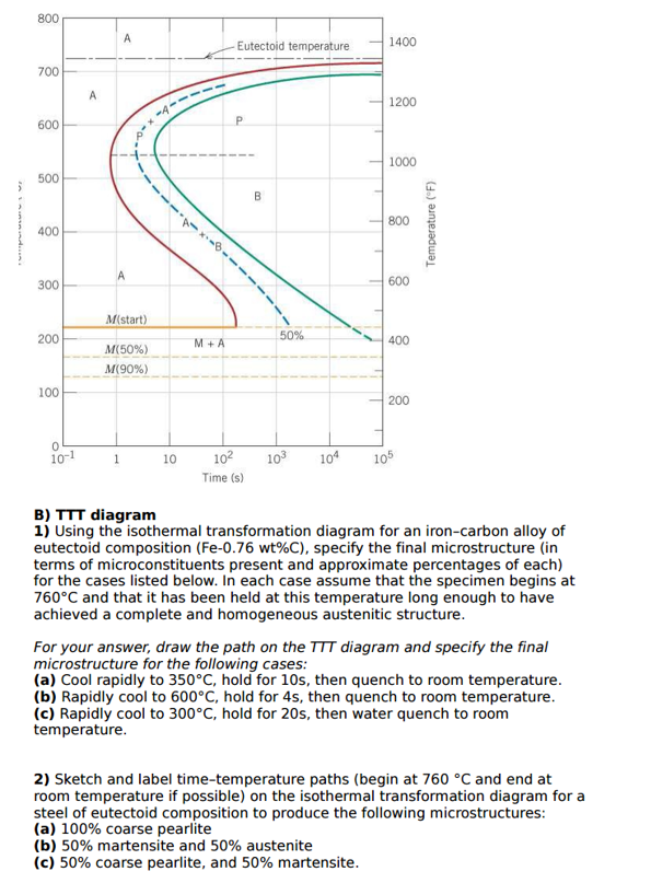
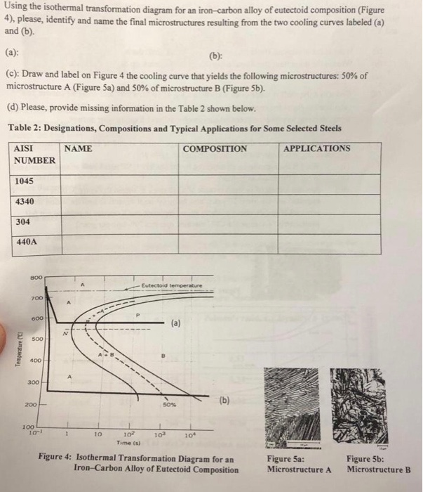
Solution we are called upon to consider the isothermal transformation of an iron carbon alloy of eutectoid composition. Ttt diagrams give the kinetics of isothermal transformations. Though usually used to represent transformation kinetics for steels.
On the isothermal transformation diagram for a 045 wt c fe c alloy sketch and label the time temperature paths to produce the following microstructures. Of materials science and engineering 20. So here is our isothermal transformation diagram for.
F temperatures for martensite. The eutectoid steel composition. Using the isothermal transformation diagram for an ironcarbon alloy of eutectoid composition shown in the figure describe the final microstructure constituents present and approximate percentages of each of a small specimen that has been subjected to the following timetemperature treatments.
We have plotted along the x axis the time and its in the scale of logarithms and. Ttt diagram stands for time temperature transformation diagram. 100 79 ratings using the isothermal transformation diagram for an ironcarbon alloy of eutectoid composition figure 1022 specify the nature of the final microstructure in terms of microconstituents present and approximate percentages of each of a small specimen that has been subjected to the following timetemperature treatments.
The absolute layer thickness depends on the temperature of the transformation. The thickness of the ferrite and cementite layers in pearlite is 81. A from figure 1022 a horizontal line at 550 c intersects the 50 and reaction completion curves at about 25 and 6 seconds respectively.
Davenport and bain were the first to develop the ttt diagram of eutectoid steel. The complete isothermal transformation diagram for an iron carbon alloy of eutectoid composition. 2 rate of transformation.
The higher the temperature the thicker the layers. An isothermal transformation diagram is only valid for one specific composition of material and only if the temperature is held constant during the transformation and strictly with rapid cooling to that temperature.
Time Temperature Transformation Ttt Curves
 Isothermal Transformation Diagram 4340 Alloy Steel
 Metals Free Full Text Method To Evaluate The Kinetics Of Bainite
 Solved Using The Isothermal Transformation Diagram For An
 The Atomic Packing Factor Is Defined As The Ratio Of Sphere Volume
 Solved Using The Isothermal Transformation Diagram For An
Time Temperature Transformation Ttt Curves
 Time Temperature Transformation T T T Diagram
 What Is The Difference Between Cct And Ttt Curve By An Easy Example
Introduction To Engineering Materials Engr2000 Chapter 10 Phase

Isothermal Transformations In Ductile Iron A Thesis Presented To The
Prediction Of Ttt Curves Of Cold Working Tool Steels Using Support
![]() Peak Movement Of A C 2 0 0 And B A 2 0 0 With The Isothermal
Peak Movement Of A C 2 0 0 And B A 2 0 0 With The Isothermal
 Steel Wiki Heat Treatment Interstahl Stahlhandel
Using Isothermal Transformation Diagram
 Continuous Cooling Transformation Wikipedia
 Ttt Diagram Example Engineering Materials Youtube
 Time Temperature Transformation T T T Diagram
![]() Isothermal Transformation Diagrams Ppt Video Online Download
Isothermal Transformation Diagrams Ppt Video Online Download
0 Response to "Using The Isothermal Transformation Diagram"
Post a Comment