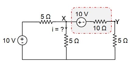
Consider The Circuit Diagram In The Figure
While kirchhoffs junction law is needed only when there are one or more junctions in a circuit kirchhoffs loop law is used for analyzing any type of circuit as explained in the following tactics box. Findathe current in the r 1 20 resistor andbthe potential di erence between points aand b.

R 3 100 v 250 v.
Consider the circuit diagram in the figure. This is where i am stuck. 180 v v r 4 400 r 1 200 r 2 300 3 100 label the voltage v 180 v and the resistors. Modify the program circuit1 to solve the circuit in problem 22 figure 28 31 of the textbook by fishbane et al.
Show transcribed image text 13 problem 5. Consider the circuit shown in figure p2129. Calculate the power delivered to each resistor in the circuit shown in figure p2131.
Tactics box 231 using kirchhoffs loop law 1. I know that i am supposed to solve. Switch s1 is then opened and the charged capacitor is connected to the uncharged capacitor by closing s2.
If an answer is a direction up down left right in or out give an explanation justifying your answer. When the bar is at position x what is the magnetic flux through the closed circuit. Consider the circuit shown in the figure below where c1 400 µf c2 700 µf and δv 180 v.
S1 and s2 are switches. Express all of your quantitative answers in terms of some or all of w x v andor b only. A find the current flowing through the 5 ω resistor.
Consider the following circuit diagram. Draw a circuit diagram. Consider the arrangement shown in the diagram.
C find the power dissipated in the 8. Modify the program circuit1 and solve the circuit shown in figure 28 12 of the textbook by fishbane et al. B find the potential difference across the 3 ω resistor.
By a circuit the sum of these potential differences must be zero. Capacitor c1 is first charged by closing switch s1. A conducting bar slides along a u shaped conducting r.
In the circuit shown in the figure four identical resistors labeled a to d are connected to a battery as shown. 7 4 5 6. For r1 r2 r3 1 ohm r4 r5 r6 2 ohm and e 1 v.
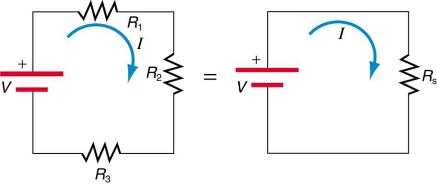
Analyzing Circuits Via Source Transformation
 Wiring Diagram Wikipedia
Computer Setup
 Passive Elements Renesas Electronics
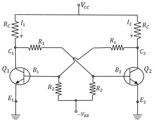 Pulse Circuits Bistable Multivibrator

 Resistors In Series And Parallel College Physics
Students Understanding Of Direct Current Resistive Electrical
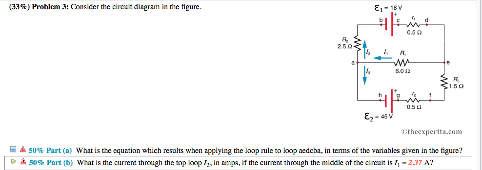 Solved 33 Problem 3 Consider The Circuit Diagram In T
 Design Guidelines For A Power Factor Correction Pfc Circuit Using
Ph203 Chapter 23 Solutions Tactics Box 23 1 Using Kirchhoff S Loop Law
 Capacitors Learn Sparkfun Com

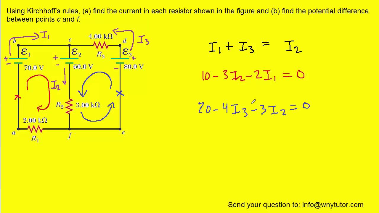 Using Kirchhoff S Rules Find The Current In Each Resistor Shown In
 365sp17hw9 Solution Me 365 Out Homework Set 9 Spring 2017 Due 1 Am
 R L C Circuit
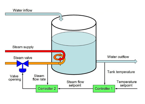 Fundamentals Of Cascade Control Control Engineering
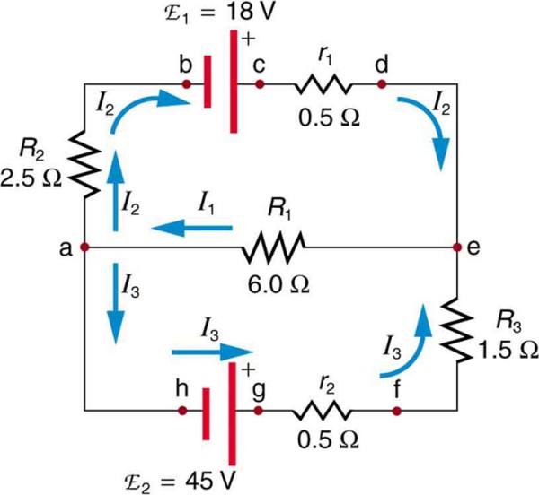 Kirchhoff S Rules Physics
 Bcs Wiring Diagram Online Wiring Diagram
 How To Use A Breadboard
0 Response to "Consider The Circuit Diagram In The Figure"
Post a Comment