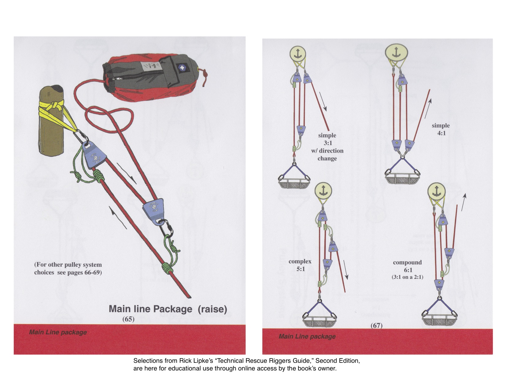
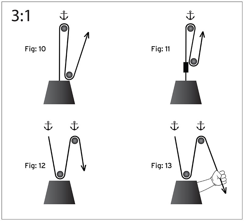
3 To 1 Pulley System Diagram
Home engine 3 1 engine diagram pulley system. By the same token a 31 system multiplies the force x3 but we pull 3 of rope per 1 of travel for the resistance.
 Block And Tackle Wikipedia
Problem 3123 point the figure shows a stationary shaft and pulley system subject to the dimension.
3 to 1 pulley system diagram. Solved problem 3123 point the figure shows a stationary. You could have the gear in the back of your truck and one day get stuck in the snow. Imagine pulling through 27 of rope to move the resistance only 1.
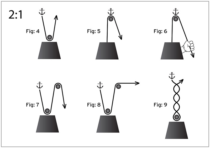
3 1 engine diagram pulley system. That image 3 to 1 pulley system diagram fabulous pulley previously mentioned can be labelled with. Dont however confuse the 31 with the similarly shaped 21 with a cod pulley or a 21 piggyback system.
The pulley system shown is used to store a bicycle the pulley system shown is used to store a bicycle in a garage. By placing the pulley at b you will make optimum use of the pulley and the resulting efficiency and force advantage ratio will be maximized. 3 to 1 pulley system feb 13 2019.
It is shared by brenda botha in the best field. Cable pulley diagram wiring diagram data schema rope pulley diagram wiring diagrams hubs cable lock diagram cable pulley diagram. Mechanical advantage explained educated climber this setup differs from the zrig setup in that the actual rope attached to the load does not integrate into the ma system here the 51 attaches to the.
We noticed it from reliable resource. 1024 x 768 pixel. Third system of pulleys.
A 3 1 is a go to pulley for low angle rescue or even in your garage. The procedure is followed on to keep the relative position of pulley 3 constant and string 3 is pulled across a distance of 2 3x x 7x 2 3 1x and finally string x4 which is actually the effort crosses a distance of 2 7x x 15x 2 4 1x meters. The following diagrams of 31 simple pulley systems have the pulleys labeled as a and b.
Listed below are some of highest rated 3 to 1 pulley system pictures on the internet. Three to one systems are often called z rigs due to their shape. Pulley systems are a great thing to learn.
If the bicycle is hoisted via a winch that winds the rope at a rate mms determine the vertical speed of the bicycle. To find out all images in new release pictures of 3 to 1 pulley system diagram graphics gallery please stick to this hyperlink. 3 to published simply by charles washington on 2014 03 02 025318.
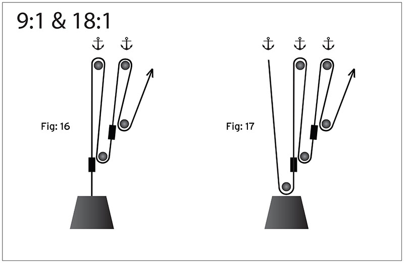
The following illustrations show 31 systems without and with a cod pulley. It is entirely possible to create systems offering 91 and even 271 advantage by piggybacking one system on another.
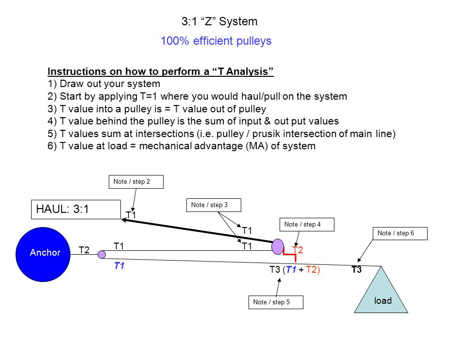
 3 1 Z System 100 Efficient Pulleys Instructions On How To Perform
3 1 Z System 100 Efficient Pulleys Instructions On How To Perform
 Elegant Of How To Make Sun Path Diagram Diva Grasshopper 02 Diagrams
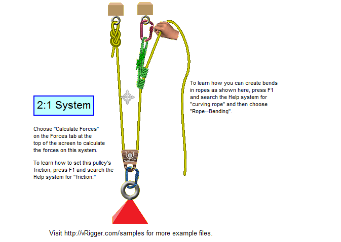
 Sample Vrigger Files
.jpg) A Pulley System Has A Velocity Ratio Of 3 And Efficiency Of 80 Draw
A Pulley System Has A Velocity Ratio Of 3 And Efficiency Of 80 Draw
 Pulleys And Mechanical Advantage Systems Cmc Pro
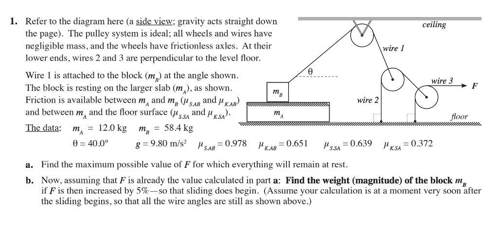 Solved 1 Refer To The Diagram Here A Side View Gravity

 Pulley Systems Flaschenzug In 2019 Tools Pulley Design Ideas
 File Four Pulleys Svg Wikipedia
 Patc Ms A More Efficient 3 1 Pulley System
 Dmm Professional Resistance Is Futile
 Dmm Professional Resistance Is Futile
 Block And Tackle Wikipedia
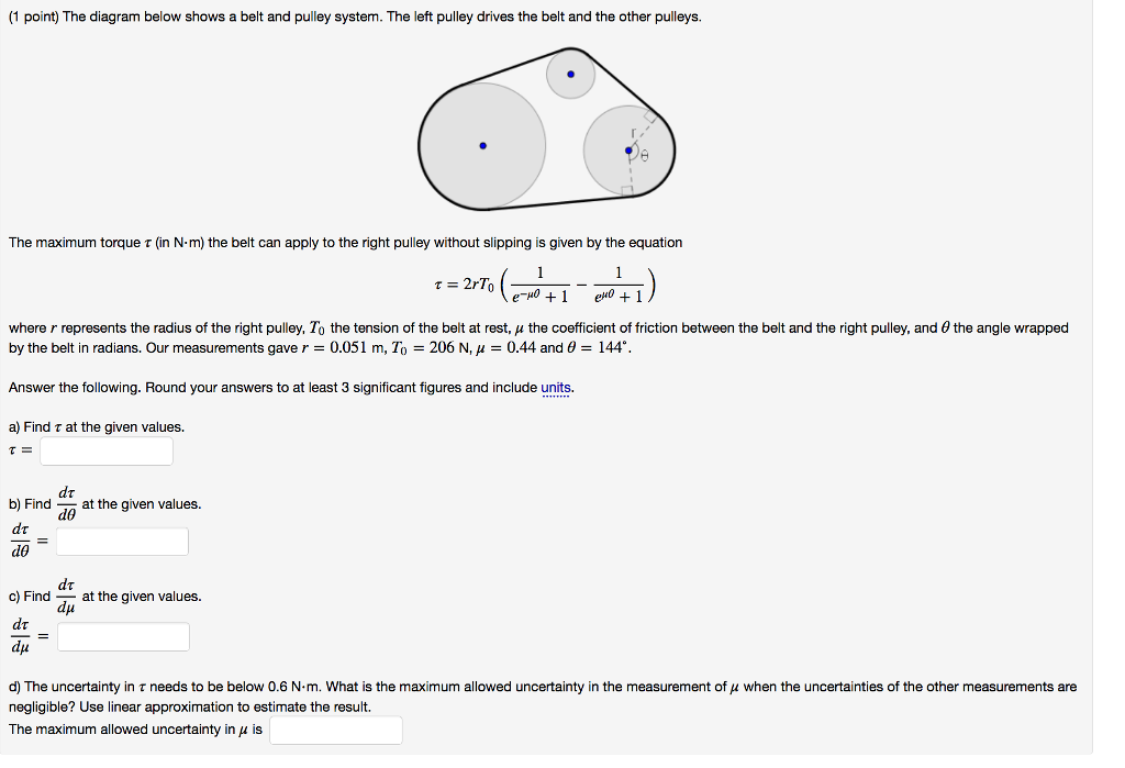 Solved 1 Point The Diagram Below Shows A Belt And Pulle

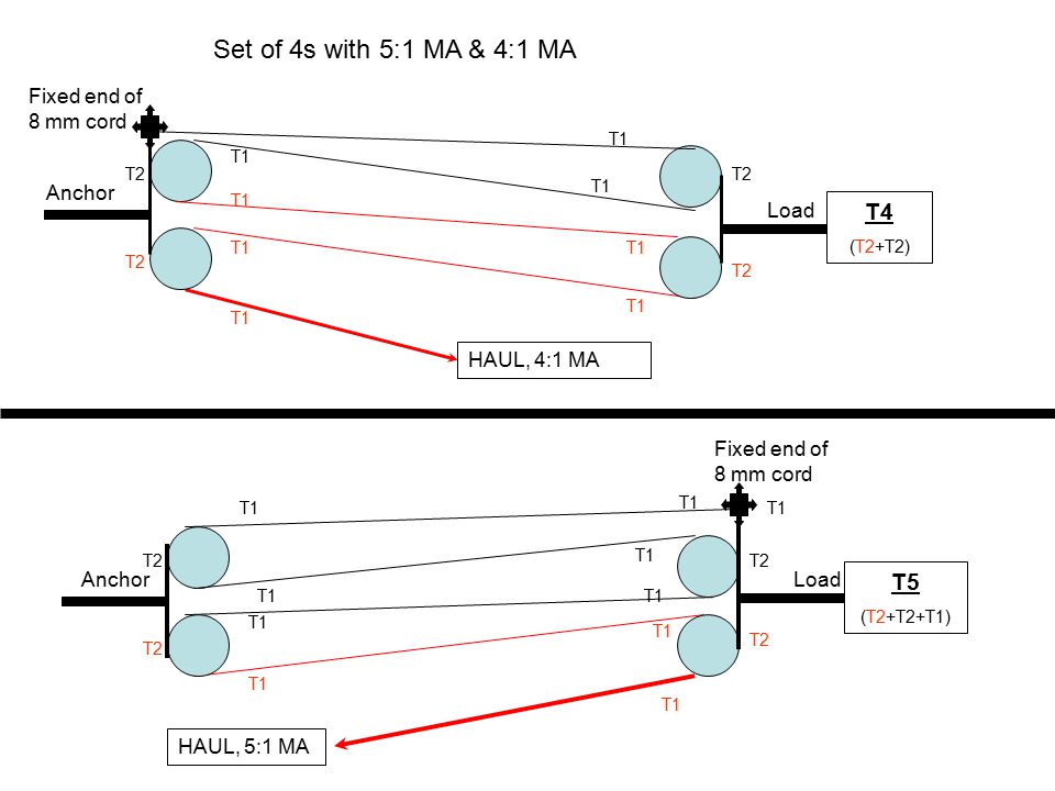
 M 4 Pulley Systems
 Some Sar Links
 Mechanical Advantage Systems A Must Know Skill Set The Wild Guide
 Dmm Professional Resistance Is Futile
Crevasse Rescue No 3 Haul Systems For Crevasse Rescue Petzl Usa
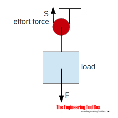
 Draw A Diagram Of A Pulley System With M A 8and One Pulley Is Fixed
 Pulleys
0 Response to "3 To 1 Pulley System Diagram"
Post a Comment