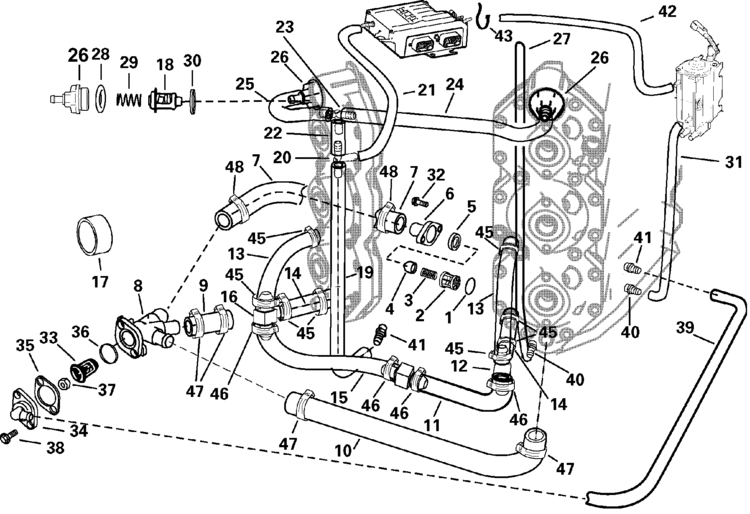
Johnson Outboard Cooling System Diagram
I am troubleshooting the cooling system on a 1980 johnson 15 hp outboard. My guess is blockage or stuck tstat.
 Johnson 6hp 1967 Outboard Part 3 Islander Sailboat
The big exhaust hole at 5 oclock of the bottom cylinder is for the cylinder head water to exit to exhaust.

Johnson outboard cooling system diagram. The waterpump is new installed correctly and pumping. The long housing between the powerhead and the lower unit is called the exhaust housing. Our products johnsonevinrude cooling system cooling system parts for johnsonevinrude outboards water pump kit with housing johnson evinrude v4 v6 18 3315 2.
1977 evinrude 70 cooling system. The large rectangular exhaust hole at 6 oclock of the bottom cylinder must have a restriction so that the cylinders do fill up with water before exiting. Johnson evinrude mercury mariner force chrysler yamaha mercruiser omc cobra.
I have removed the thermostat and housing and i can get water to flow backwards from the tell tale through the waterjacket and out the thermostat opening. Mallory marine thermostats are designed to provide superior reliability and performance in marine applications. There are a couple of things pertaining to the outboard cooling system.
Just got a few questions as i learn about these outboards how hot should they run. And why is one bank running much hotter than the other. There is a inner housing within it that has a heavy duty seal around the bottom of it or heavy duty seals around a inner extension between the housing and the lower unit.
Water flow diagram for johnson 6 hp. 1996 150 hp evenrude hose diagrams manual ebooks evinrude johnson outboard parts drawings how to videos 1996 150 hp evenrude hose diagrams. Seastar solutions sierra impeller repair kit for johnsonevinrude cooling systems.
Proper cooling system operation is critical to achieve smooth engine idle and maximum fuel efficiency. Cooling system news cooling system yamaha outboard cooling system yamaha outboard images. Water is inducted through the lower unit by a water pump impeller and then forced upward to circulate throughout the powerhead and eventually exits through the exhaust system.
Yamaha 4 stroke outboard wiring diagram wiring diagram 70 hp yamaha 2 stroke wiring diagram toyskids co u2022.
 Outboard Motor Cooling System Diagram Great Installation Of Wiring
Power Boat Diagram Wiring Diagram Database
 Eveinrude 70hp Cooling System Diagram Great Installation Of Wiring
70 Hp Evinrude Fuel System Diagram Free Wiring Diagram For You
Yamaha Outboard Cooling System Diagram Best Wiring Library
 T5 Engine Diagram Wiring Library
Omc Shifter Diagram 1 Wiring Diagram Source
 Install Boat Engine Cooling System Diagram Toyskids Co
Cooling Water Evinrude Cooling Water Flow
Hp Wiring Diagram Schematic Diagram
Johnson Outboard Parts Diagram For 1995 120 Free Wiring Diagram
 Outboard Cooling System Diagram Toyskids Co
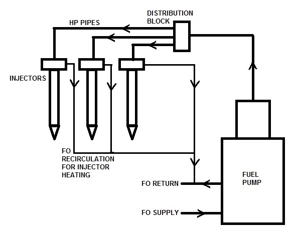 Outboard Cooling System Diagram Toyskids Co
 Outboard Cooling Water Youtube
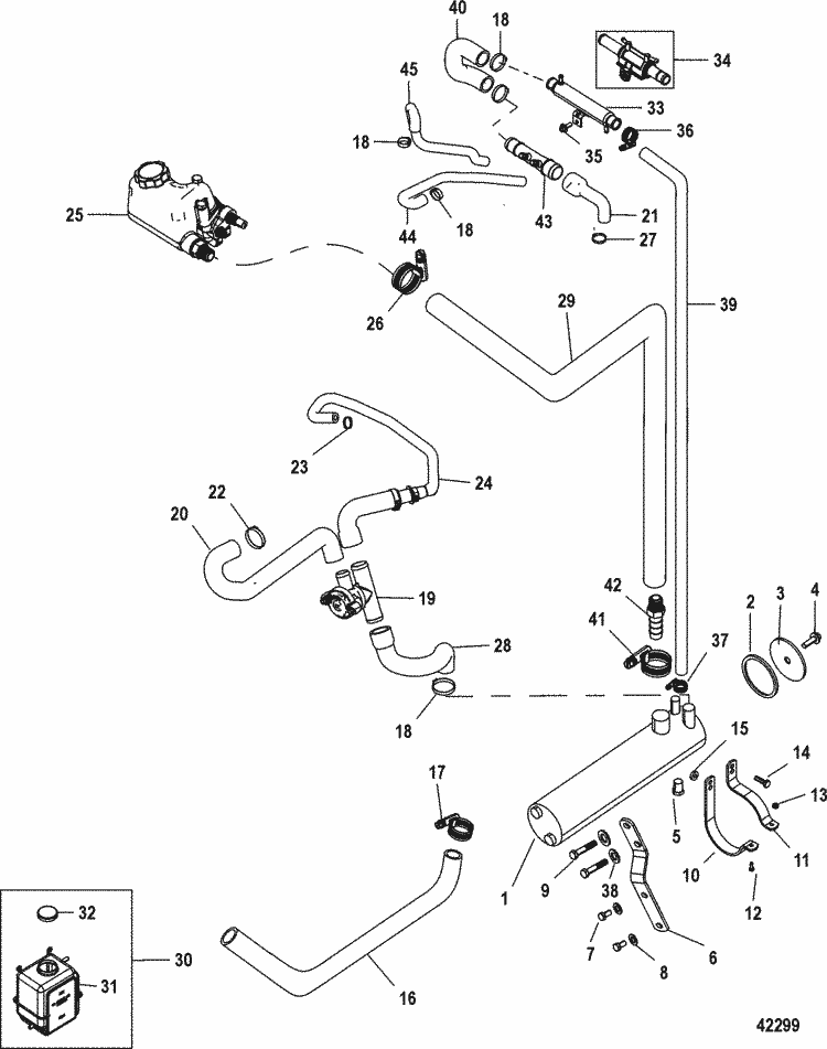 Outboard Cooling System Diagram Toyskids Co
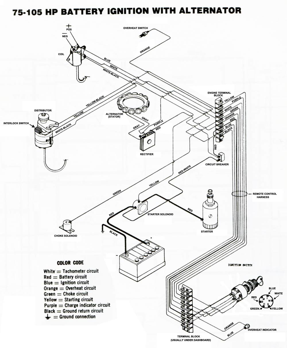 Power Boat Diagram Wiring Diagram Database
50 Luxury Johnson Outboard Cooling System Diagram Abdpvtltd Com
 Diagram Of 2001 F115tlrz Yamaha Outboard Fuel Injection Nozzle
 Engine Wiring Diagram Yamaha 40 Hp Outboard Wiring Diagram
Engine Wiring Diagram Yamaha 40 Hp Outboard Wiring Diagram
115 Wire Harness Diagram Fuse Box Wiring Diagram
Johnson Outboard Cooling System Diagram Inspirational 74 On Water
0 Response to "Johnson Outboard Cooling System Diagram"
Post a Comment