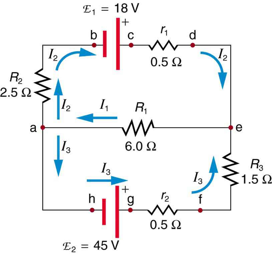
Consider The Circuit Diagram Depicted In The Figure
On the diagram it is represented by the vector labeled. On the diagram it is represented by the vector labeled v0.
 Efficiently Design An Op Amp Summer Circuit Electronic Design
R 1 91.

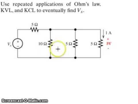
Consider the circuit diagram depicted in the figure. 0 ω r 3 16. For the action depicted in the figure figure 2 indicate the direction of the induced current in the loop clockwise counterclockwise or zero when seen from the right of the loop. Now consider a diagram describing a parallel ac circuit containing a resistor a capacitor and an inductor.
When the switch is open a current i1 is drawn from the battery. Consider the circuit as shown in the figure. This time the voltage across each of these elements of the circuit is the same.
What equation do you get when you apply the loop rule to the loop abcdefgha in terms of the variables in the figure. View questions only view questions with strategies. E r s 91 ω 16 ω 16 ω 91 ω find the value of r.
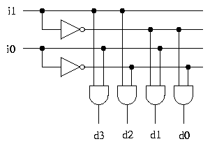
Consider the circuit diagram depicted in the figure. Problem 1 question sr latch draw the output and timing diagram of a a nor and b nand implementation of an sr latch for the input signals depicted in figure p62. B if the current through the top branch is i 2 0605 a what is the current through the bottom i 3 in amps.
The face of the south pole will become the north pole so there will be a force of attraction between them which makes the motion of the coil opposed. When the switch is closed the resistance of the external circuit decreases because there are now two resistors connected in parallel. Consider the research project depicted in figure 7 2.
0 ω r 2 16. This time the voltage across each of these elements of the circuit is the same. E r s r 1 r 2 r 3 r 4 let.
0 ω r 4 91. 008 100 points the equivalent resistance of the circuit in the figure is r eq 63. Eecs 31cse 31ics 151 homework 5 questions with solutions.
A what equation do you get when you apply the loop rule abcdefgha in terms of the variables in the figure. 0 ω and r eq 63. If the current through the top branch is i2 039 a what is the current through the bottom i3 in amps.
Based on the information provided which activity can you delay by one day without impacting the expected completion date for the project. Consider the circuit diagram depicted in the figure. Consider a diagram describing a parallel ac circuit containing a resistor a capacitor and an inductor.
From equation 1 the voltage drop v1 across the battery is given by.
 In Defense Of The Current Feedback Amplifier Edn
 Kirchhoff S Rules Physics
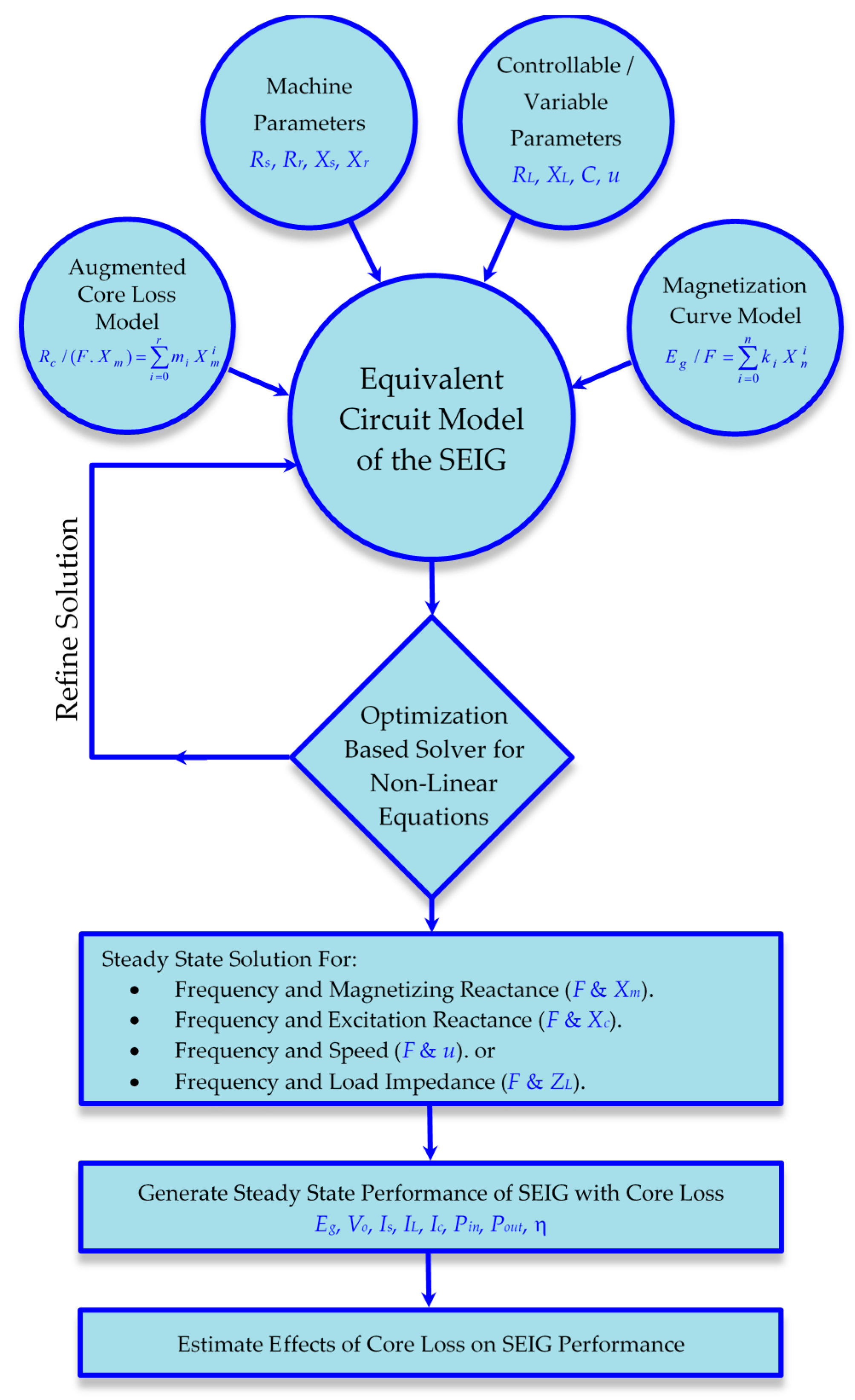 Energies Free Full Text Magnetization Dependent Core Loss Model
 Evaluating Internal Resistance In Circuits Electric Circuits
Kirchhoff S Rules Multi Loop Direct Current Circuits
 Example Application Of Kirchhoff S Voltage Law Kvl Current Law
Assignment 10 Solution 1 Consider An Op Amp With Input Offset

Chapter 17
Chapter 5 Synchronous Sequential Logic
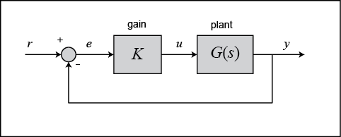
Figure 2 1 A Block Diagram Representation Of A System B Block
Examples Of Solved Problems For Chapter 3 5 6 7 And 8
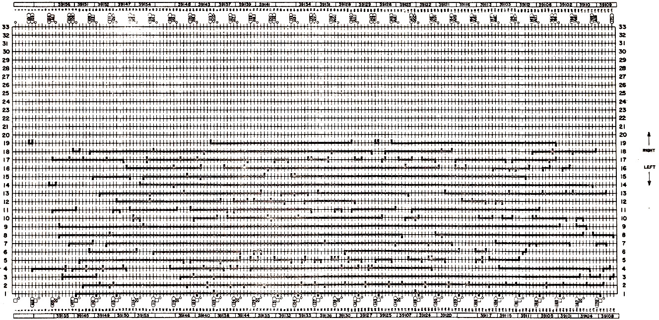 Virtual Agc Electrical Mechanical Page
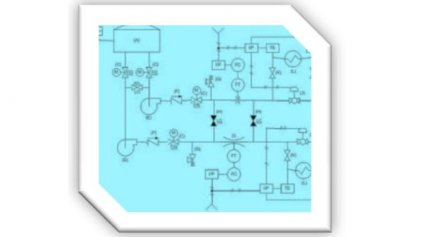 Interpreting Piping And Instrumentation Diagrams Symbology Aiche
Km26 Magnetic Level Gauges Magnetic Level Gauge Magwave Dual
 Cs379c 2018 Class Discussion Notes


 Wien Bridge Oscillator Tutorial And Theory
0 Response to "Consider The Circuit Diagram Depicted In The Figure"
Post a Comment