Marine Hydraulic Steering System Diagram
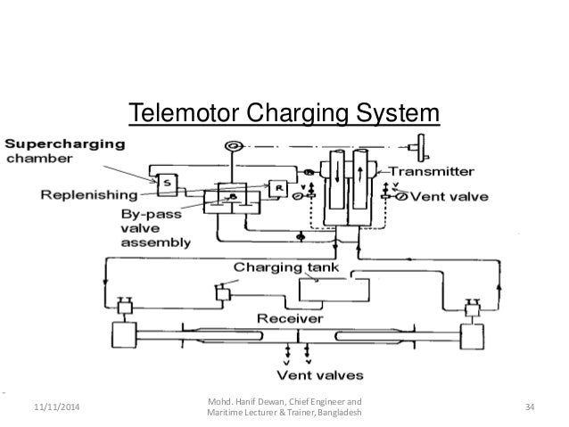
The autopilot cylinder unloader valve is a line mounted valve that is used to bypass the hydraulic steering cylinder to enable the boat to be steered manually. A hydraulic steering gear consists of a bridge control which applies helm an engine control which is operated jointly by the helm and hunting gear when fitted and a power pump and rudder actuator which constitutes the steering engine.

Better feel for the road meet better feel for the water.

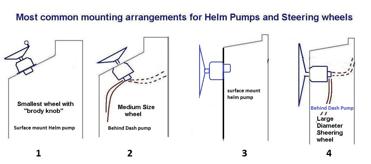
Marine hydraulic steering system diagram. Below is an example of a jog lever steering system complete with provisions with a backup steering wheel helm pump. The internal valve assembly acts as a check valve. The use of small pistons and ball bearings makes the pump action very smoothnothing like a normal piston pump.
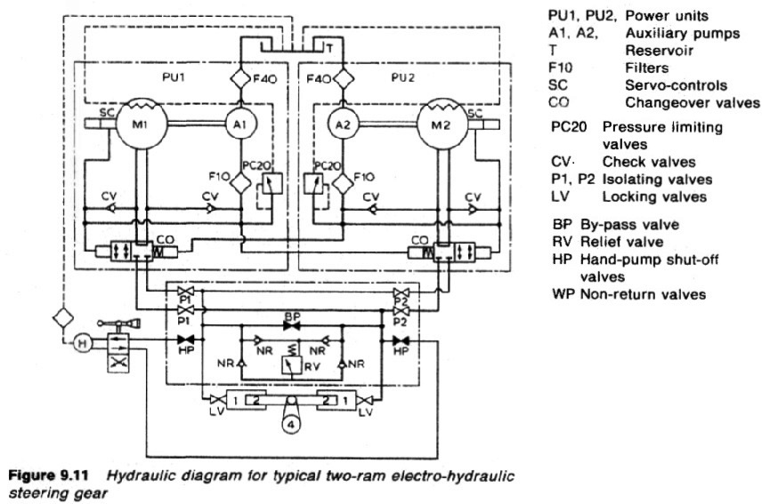
Hose installation 12 connecting hose to cylinders 12 connecting hose to steering helm 13 system filling and purging 14 single steering station and cylinder scheme 15 multiple steering station and cylinder scheme 16 summarized alert instructions and maintenance 17 technical information 18 troubleshooting guide 19. Hardin marine suggests the use of part 137 9309 mandrel for proper installation of hose end. Consists of electric motor driven pumping units a divided reservoir with tank accessories directional control valves system motion control relief and check valves gauges and suction and return line filtration.
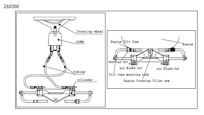
Remote mount reservoir installation before installing the remote mount power steering reservoir the stock fill cap on the power steering pump must be removed and replaced with the power steering return dump cap provided. Much like the power steering system in your car or truck. In this example we chose to use two accu steer hrp 35 reversing pumps with the lines combined.
Uses hydraulic pumps and fluid to take the effort out of steering. In this article we will learn about the hydraulic steering systems used in marine applications. This 12 watt solenoid operated valve is available in 12 and 24 vdc and can be used in systems up to 72 bar.
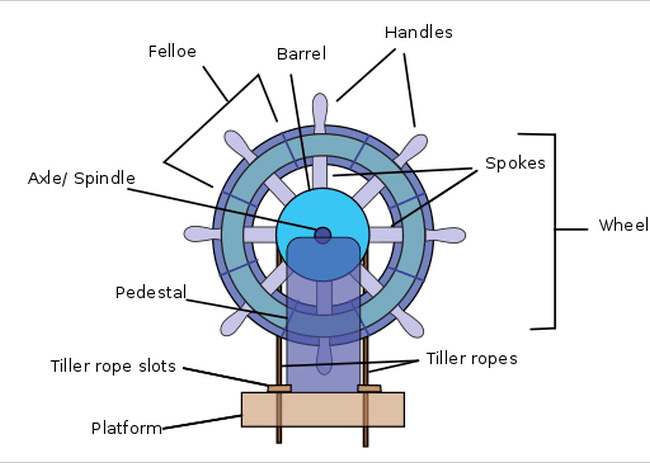
Steering gear system the steering gear system has three main parts. Parts of a hydraulic system. Relatively new to the marine market.
Hydraulic power unit hpu. To control the read more. Marine jog lever steering.
Transmission to the rudder stock. With power steering you have a 2nd hydraulic pump that is driven by an external power source an engine or electric motor not just your arm and through a series shuttles block or pilot operated valves hoses etc the output of this secondary pump is fed into the steering system to supplement. The pump is activated by turning the steering wheel which causes a swash plate to press on a series of small piston pumps.
Marine autopilot cylinder unloader valve. Slide 2 of 4.
 Marine Steering Gear And Solas Requirements
 Teleflex Seastar Outboard Hydraulic Steering
 Technical Help Hydraulic Steering Bleeding Proceedure


Rose S Marine Products Steering
 Teleflex Capilano Inboard Hydraulic Steering Systems
 Amazon Com Seastar Hs5157 Front Mount Hydraulic Steering Cylinder
 Marine Hydraulic Steering Systems Seaboard Marine
 Teleflex Seastar Outboard Hydraulic Steering Catamaran Pontoon

 Teleflex Capilano Inboard Hydraulic Steering Systems
 Marine Hydraulic Steering Systems Seaboard Marine

 Understanding Steering Gear In Ships
 Tips On Hydraulic Steering For Outboards Boats Com

0 Response to "Marine Hydraulic Steering System Diagram"
Post a Comment