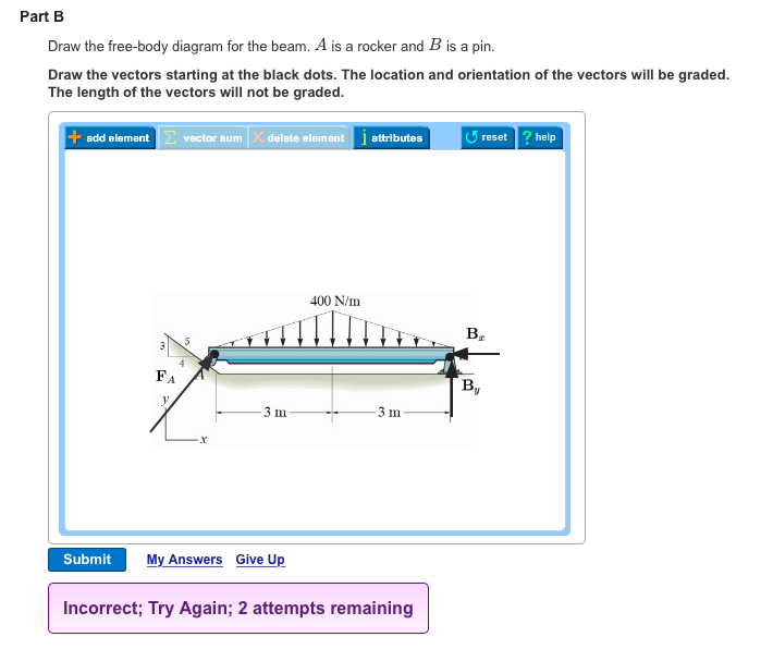
Draw The Free Body Diagram For The Beam A Is A Rocker And B Is A Pin
Rigid body equilibrium free body diagrams and the equations of equilibrium. 19 37 free body diagrams wednesday october 3 2012 new support conditions.
 What Are Differences Between Support Types Roller Pinned Fixed
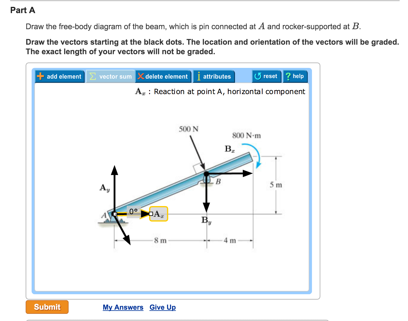
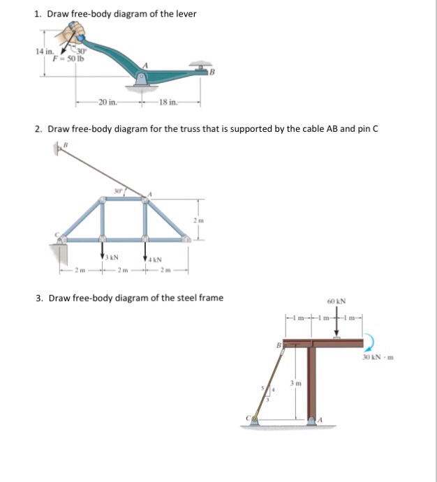
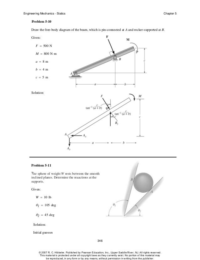
Draw the free body diagram of the beam which is pin connected at a and rocker supported at.

Draw the free body diagram for the beam a is a rocker and b is a pin. A is a rocker and b is a pin. Draw the free body diagram for the truss. 1 contd free body diagrams description support at a is a fixed wall the wall exerts three reactions on the beam.
Draw the vectors starting at the black dots. Part a draw the vectors starting at the black dots. There are a number of ways to draw pin connections here is a pin connecting two members.
When holding the 5 1b stone in equilibrium the. Free body diagrams are consequently often called equilibrium diagrams. 1 contd free body diagram example.
Each force arrow in the diagram is labeled to indicate the exact type of force. The location and orientation of the vectors will be graded. 5 12 53 equations of equilibrium.
At point h link. The line of action of the force is along the axis of the link. Conditions for rigid body equilibrium free body diagrams.
Draw the free body diagram for the beam. The beam has a mass of 100kg. A is a rocker and b is a pin.
Draw the free body diagram for the beam. The length of the vectors will not be graded. Draw the free body diagram of the uniform.
A draw the free body diagram of the beam. An example of a free body diagram is shown at the right. Draw the free body diagram for the beam.
The beam has a mass of 100kg. Draw the vectors starting at the black dots. The location and orientation of the vectors will be graded.
The length of the vectors will not be graded. A is a pin and b is a rocker. 222 ch 6 drawing a free body diagram.
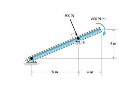
At this support there is a force that either pushes or pulls on the system. 500 n 800n m 5m prob. The above diagrams which show the complete system of applied and reactive forces acting on a body are called free body diagrams.
It is generally customary in a free body diagram to represent the object by a box and to draw the force arrow from the center of the box outward in the direction that the force is acting. Draw the free body diagram of the jib crane ab which is pin connected at a and supported by member link bc. The whole system of applied and reactive forces acting on a body must be in a state of equilibrium.
Problem 53 the beam is subjected to a load f d 400 n and is supported by the rope and the smooth surfaces at a and b. Draw the free body diagram of the beam whic pin connected at a and rocker supported at b. Roller or rocker.
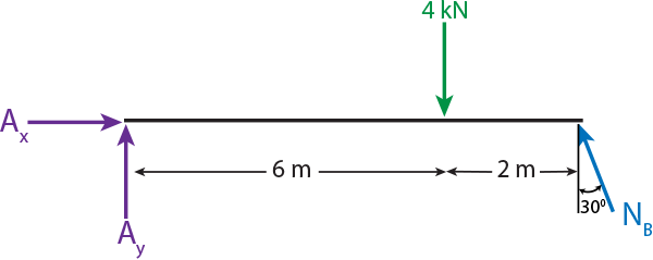
Solution
 Draw The Free Body Diagram For The Beam A Is A Rocker And B Is A Pin
T A B The Free Body Diagram The Concurrent System
 Solved Part B Draw The Free Body Diagram For The Beam A
 Solved Part A Draw The Free Body Diagram Of The Beam Whi
Engineering Mechanics Statics 12th Ch05 Solutions Studocu
Wiring Diagram On Off Switch And Led Rocker Wiring Diagram
 Cyclic Testing Of A Buckling Restrained Braced Frame With
 Determine The Horizontal And Vertical Components Of Reaction At The
 Statics Lec 5 1 Rafey Imtiaz Academia Edu
Solution
Solution
Solution
 Solved Draw The Free Body Diagram Of The Beam Which Is P
 Hw 17 S16 Key Draw The Free Body Diagram Of The Beam And Describe
 Wiring Diagram On Off Switch And Led Rocker Wiring Diagram
Solution
Section 5 1 5 2
Section 5 1 5 2
Engineering Mechanics Statics 12th Ch05 Solutions Studocu
 Hibbeler Chapter5
0 Response to "Draw The Free Body Diagram For The Beam A Is A Rocker And B Is A Pin"
Post a Comment